en
16
Operation via Switch
(is an emergency function, not all functions are available)
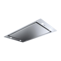
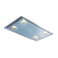
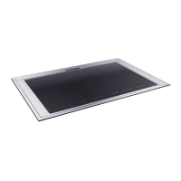
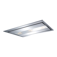
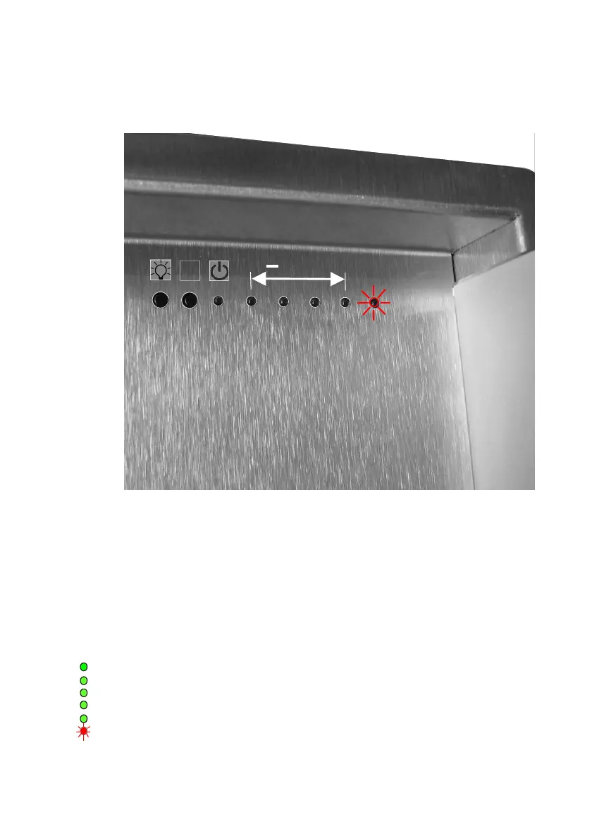
The control panel Located on the Ceiling Device below the Pane. The control panel
consists of 2 buttons with 6 LED’s. The exhaust power is controlled over the switch
panel. Among the lighting additional options are also controlled over the switch panel
by some extractor hoods.
+
a b
c
1
2
3 4
f
a
= Pressing the button: = Light ON
Longer push: = results in dimmed light (not with LED).
Pressing the button again: = Light OFF
b
= Pressing the button 1x : = fan ON, Level 1, LED c + 1 ON
Pressing the button 2x : = Level 2, LED c + 1-2 ON
Pressing the button 3x : = Level 3, LED c + 1-3 ON
Pressing the button 4x : = intensive Level LED c + 1-4 ON
intensive level (motor switches back
to level 3 after 5 minutes)
LED Indicators:
Information regarding the operating conditions of the hood can be read on the device’s
LED indicators:
Cool Down green LED
Level 1 green LED
Level 2 green LED
Level 3 green LED
Intensive Level green LED
Filter Saturation Indicator red LED
Filter Saturation : Button min. 10 sec. pressures to a
red LED goes off (reset)The metal
filter must be cleaned regularly (at least every 14 days) to prevent a fire hazard. The
necessary cleaning of the grease filter is also shown via the LED indicator: the red LED
on the ceiling unit lights up as of 15 operating hours.
 Loading...