Please be subject to the actual product purchased.
The above indoor and outdoor units’ picture is just for your reference.
F
A
C
E
D
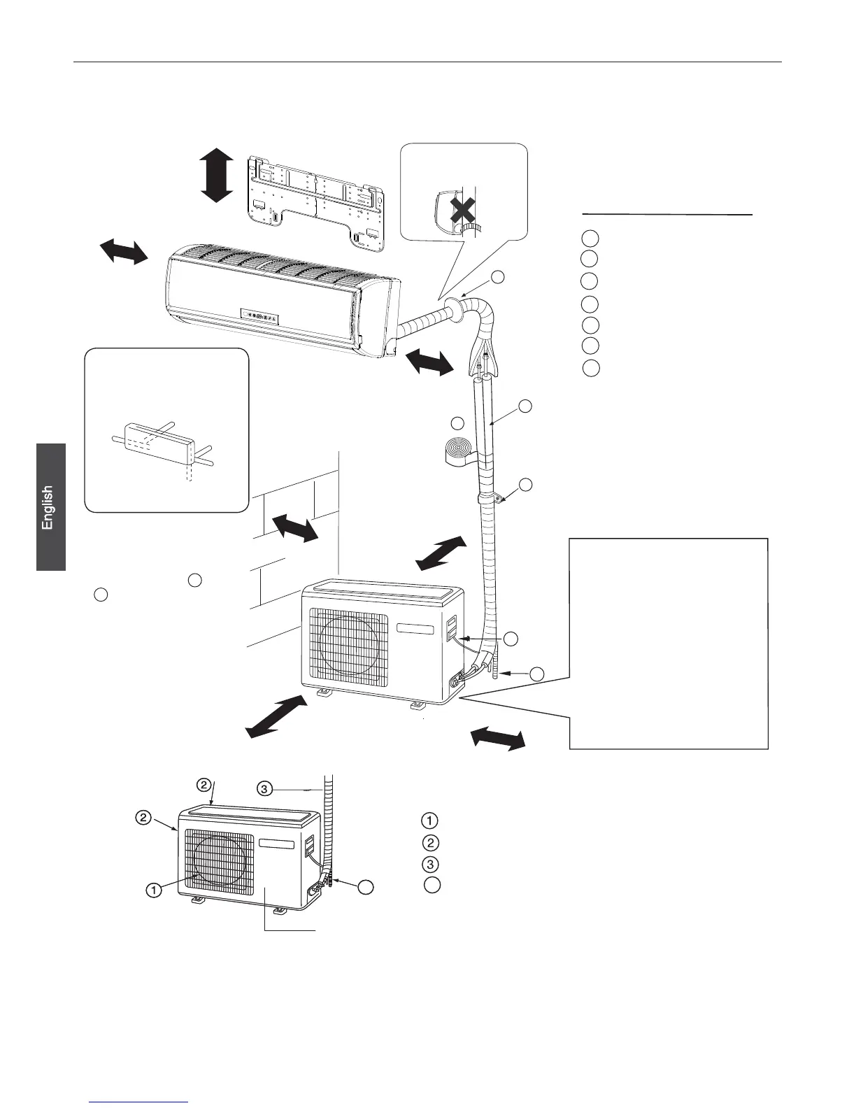
Optional parts for piping
Non-adhesive tape
Adhesive tape
Saddle(L.S)withscrews
Connecting electric cable
for indoor and outdoor
Drain hose
Heating insulating material
Piping hole cover
Fixing of outdoor unit
Fix the unit to concrete or blockƽ
with bolts (10mm) and nuts firmly
and horizontally.
When fitting the unit to wall
ƽ
surface, roof or rooftop, fix
asupportersurelywithnails
or wires in consideration of
earthquake and strong wind.
If vibration may affect the
ƽ
house, fix the unit by attaching a
vibration-proof mat.
The marks from to
in the figure are the
parts numbers.
Thedistancebetween
theindoorunitandthe
floorshouldbemore
than 2m.
The models adopt HFC free refrigerant R410A.
more than
10cm
more than 15cm
more than 10cm
more than 20cm
more than
20cm
more than 25cm
more than
60cm
A
G
ƽ
ƽ
A
F
C
E
D
G
B
Arrangement of piping
directions
Rear left
Left
Rear
right
Right
Below
G
Attention must be paid to
the rising up of drain hose
Indoor/Outdoor Unit Installation Drawings
For installation of the indoor units,refer to the installation manual which was provided with the units.
(The diagram shows a wall-mounted indoor unit.)
AIR OUTLET
AIR INLET
CONNECTING PIPING AND ELECTRICAL WIRING
DRAIN HOSE
4
ƽ
Compressor(Inside of Unit)
15
 Loading...