168
Super Match
Installation Procedure
Selecting the mounting position to install the indoor units
■ Select suitable places where the outlet air can be sent to the entire room, and convenient to
lay out the connection pipe, connection wire and the drainage pipe to outdoor.
■ The ceiling structure must be strong enough to support the unit weight.
■ The connecting pipe, drain pipe and connection wire shall be able to go though the building
wall to connect between the indoor and outdoor units.
■ The connecting pipe between the indoor and outdoor units as well as the drain pipe shall be
as short as possible.
■ If it is necessary to adjust the lling amount of the refrigerant, please refer to the installation manual attached with
the outdoor unit.
■ The connecting ange should be provided by the user himself.
■ The indoor unit has two water outlets one of which is obstructed at the factory (with a rubber cap). Only the outlet
not obstructed (liquid inlet and outlet side) will be generally used during installation. If applicable, both the outlets
should be used together.
■ An access port must be provided during installation of indoor unit for maintenance.
After selecting the unit installation location, proceed the following steps:
1. Drill a hole in the wall and insert the connecting pipe and wire through a PVC wall-through tube
purchased locally. The wall hole shall be with a outward down slope of at least 1/100.
2. Before drilling check that there is no pipe or reinforcing bar just behind the drilling position. Drilling
shall avoid at positions with electric wire or pipe.
3. Mount the unit on a strong and horizontal building roof. If the base is not rm, it will cause noise, vibration or
leakage.
4. Support the unit rmly.
5. Change the form of the connection pipe, connection wire and drain pipe so that they can go through the wall hole
easily.
AD09LS1ERA
AD12LS1ERA
AD18LS1ERA
AD24LS1ERA
AD09SS1ERA
AD09SS1ERA(N) AD09SS1ERA(N)(P)
AD12SS1ERA
AD12SS1ERA(N) AD12SS1ERA(N)(P)
AD18SS1ERA
AD18SS1ERA(N) AD18SS1ERA(N)(P)
AD24SS1ERA
AD24SS1ERA(N) AD24SS1ERA(N)(P)
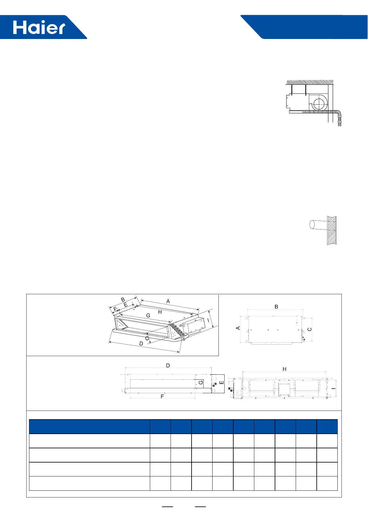
Indoor unit dimensions(unit:mm)
Unit model A B c D E F G H I
AD09LS1ERA
AD12LS1ERA
538 483.5 131 610 255 105 418 508 220
AD18LS1ERA
AD24LS1ERA
1002 483.5 131 1105 255 105 880 970 220
AD09SS1ERA AD09SS1ERA(N) AD09SS1ERA(N)(P)
AD12SS1ERA AD12SS1ERA(N) AD12SS1ERA(N)(P)
420 892 370 850 185 640 90 760 152
AD18SS1ERA AD18SS1ERA(N) AD18SS1ERA(N)(P)
AD24SS1ERA AD24SS1ERA(N) AD24SS1ERA(N)(P)
420 1212 370 1170 185 960 90 1080 152
 Loading...