172
Smart Power
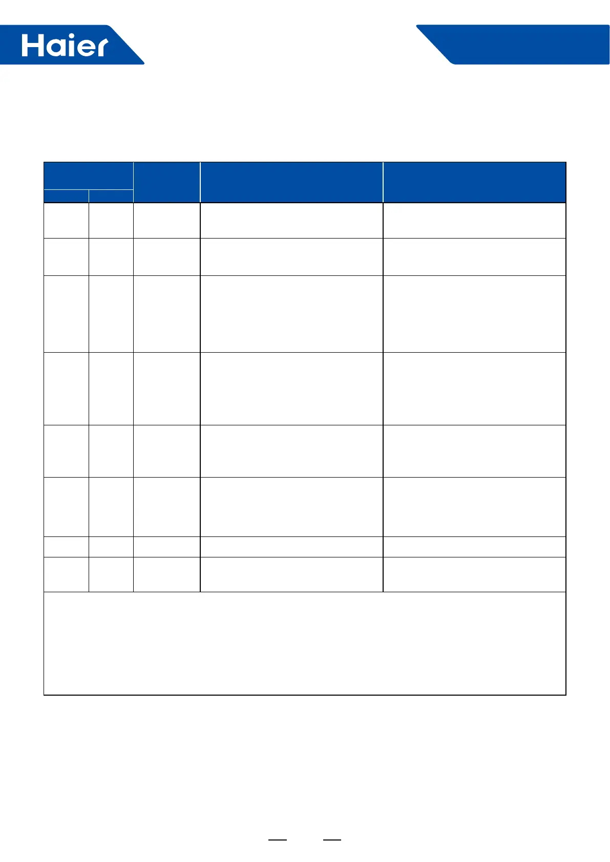
4. Failure Code
4.1 Failure code indoor unit
ABH071H1ERG ABH90H1ERG ABH105H1ERG ABH125K1ERG ABH140K1ERG
LED ash times of
indoor PCB
LR.Recever
digital display
Contents of malfunction Possible reasons
LED4 LED1
0 1 01
Malfunction of indoor unit ambient
temperature sensor
Sensor disconected, or briken, or at
wrong position, or short circuit
0 2 02
Malfunction of indoor unit piping
temperature sensor
Sensor disconected, or briken, or at
wrong position, or short circuit
0 4 04 EEPROM erong of indoor PCB
EEPROM chip disconected or broken
or wrong programmed, or PCB broken
0 7 07
Abnormal communication between
indoor and outdoor units
Wrong connection, or the wires be
disconected or wrong adress setting
of indoor unit or faulty power supply or
faulty PCB or slave unit malfunction in
MAXI system
0 8 08
Abnormal communication between
wired controller (or I.R. RECE IVER)
and indoor unit
Wrong connection or wired controller
broken, or PCB faulty
0 12 0C Malfunction of drain system
Pump motor disconnected or at
wrong position, or the oat switch,
disconnected, or at wrong position, or
the short circuit bridge disconne ted
0 13 0D Zero cross sigal wrong Zero cross sigal detected wrong
0 14 0E Indoor unit DC fan motor abnormal
DC Fan motor disconnectde or DC Fan
broken or circuit broken
Note:
1. The outdoor failure can also be indicated by the indoor unit, the checking method as follows: If the outdoorerror
code is M (DECIMAL) , the indoor unit's I.R. receiver display will show the after converted hexadecimal code of
"M+20" (DECIMAL) , for example, if the outdoor error code is 2, the indoor unit I.R. receiver display will ash the
error code 16 (2→2+20=22→change deciaml 22 to hexadecimal code, get 16)
2. LED4 is a red one on the indoor PCB, LED1 is a yellow one.
3. To get much more details about the out door unit failure, please refer to the outdoor unit trouble shooting list.
 Loading...