OUTDOOR TECHNICAL OVERVIEW
B-10
ENGLISH
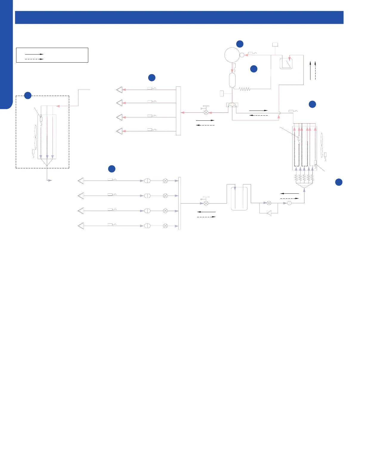
Operations
On a call for heating, the indoor unit will send the room temperature and set-point requirement to the outdoor unit ECU via the
data signal wire path. The data travels from the indoor unit to the outdoor unit via the wire located on terminal 3. The indoor
unit’s louver will open the indoor fan will remain o.
EEV valves serving indoor circuits will step to a FULL OPEN BYPASS position. Outdoor EEV valve serving outdoor coil will step
open to a pre-set metering position based upon the temperature of the outdoor air.
The outdoor unit 4 way valve will be energized. Equalization noise will be heard.
The outdoor fan motor will start.
The compressor will start in low RPS speed and gradually speed up.
Indoor fan will begin to operate at slow speed and gradually increase speed.
With the compressor operating, refrigerant will begin to ow throughout the refrigeration circuit.
The operating frequency of the compressor will be displayed on the Service Monitor Board Display.
When the compressor starts, the compressor will discharge hot gas into the oil separator. Oil will be trapped in the separator and
returned to the suction inlet of the compressor via the capillary tube assembly low pressure path.
Heating Mode Sequence of Operation
Comp-
ressor
Discharge temp.
sensor
Oil
separator
Capillary tube
High pressure
switch
4-way valve
Pipe sensor
Toci
Suction temp.
sensor
Low pressure
switch
Accumulator
Gas stop valve
Outdoor
heat
exchanger
temp.
sensor
FAN-OUT
Outdoor
ambient
temp.
sensor
Defrost
sensor
Distributor
Strainer
Check valve
Receiver
Liquid stop vavle
5/8
3/8
Strainer
Unit A liquid pipe temp. sensor
Indoor unit A
Strainer
Unit B liquid pipe temp. sensor
Indoor unit B
Strainer
Unit C liquid pipe temp. sensor
Indoor unit C
Strainer
Unit D liquid pipe temp. sensor
Indoor unit D
Unit A gas pipe temp. sensor
Unit B gas pipe temp. sensor
Unit C gas pipe temp. sensor
Unit D gas pipe temp. sensor
Indoor unit A
Indoor unit B
Indoor unit C
Indoor unit D
4-way valve coil:
OFF
ON
Refrigerant flow in cooling
Refrigerant flow in heating
FAN-IN
Indoor
ambient
temp.
sensor
Indoor
heat
exchanger
temp.
sensor
EEV A
B VEE
EEV C
EEV D
EEV O
φ2.7*φ1.0*55in
1
5
4
3
2
2
6
valve
 Loading...