12
SECTION 3. INSTALLATION
All gas installations:
The H-Series heater is to be installed with a gas connection
located on the left side (or right side, if necessary). Insert the
pipe to the gas valve through the star-slit black plastic cap in
the cabinet side. It is recommended that a ground-joint union be
installed inside (or outside if space does not allow) the heater
cabinet to facilitate servicing the burner assembly tray. See
Figure 21.
An A.G.A Certied main gas valve shutoff must be installed
outside of cabinet and within 6 feet of the heater. Gas shutoff
valve must have an l.D. large enough to supply the proper
amount of gas volume to the heater.
! NOTE: Apply joint compounds (pipe dope) sparingly and
only to the male threads of pipe joints. Do not apply joint com-
pound to the rst two threads. Use joint compounds resistant to
the action of liqueed petroleum gas. Do not over tighten the gas
inlet pipe or damage may result. See Figure 21.
To prevent dirt and moisture from entering gas valve, a sedi-
ment trap should be installed in the gas line close to the valve.
See Figure 21.
Do not use exible appliance connectors on any gas
connections unless the connector is A.G.A. approved for
outdoor installation, is marked with the BTUH capacity
(which must be equal to or greater than the heater rated
input), and the type of gas (Natural or LP) to be used.
Reduction of the gas supply pipe or tubing to the inlet of
the heater gas valve must be made at the valve only and must
match the valve inlet size (3/4”).
If more than one appliance is installed on the gas line, consult
the local gas company for the proper gas line size.
Any questions concerning the installation of the proper gas
line size can be directed to Hayward Technical Service. Tele-
phone numbers can be found in Troubleshooting Guide Section.
NATURAL GAS
The gas meter must have the capacity to supply enough
gas to the pool heater and any other gas appliances if they are
on the same pipe-line (Example: 225 meter = 225,000 BTUH).
If doubt exists as to the meter size, consult local gas utility for
assistance. Hayward will not be responsible for heaters that
soot up due to improper meter and gas line sizing resulting in
improper gas volume.
PROPANE GAS
All propane gas tanks must be located outdoors and away
from pool/spa structure and in accordance with the standard for
storage and handling of propane gas ANSI/NFPA 58 (latest edi-
tion) and applicable local codes. If propane gas tank is installed
underground, the discharge of the regulator vent must be above
the highest probable water level.
Propane tanks must be sufcient capacity to provide ad-
equate vaporization for the full capacity of the equipment at the
lowest expected temperatures. Consult a propane company
expert for correct sizing.
! NOTE: Whenever a high pressure double regulation sys-
tem is utilized for propane gas, consult a propane professional
for accurate pipe and pressure sizing. Make sure that 1st and
2nd stage regulators are large enough to handle the BTUH input
listed for the heater(s) being used.
Hayward will not be responsible for heaters that soot up due
to improper gas line or Propane tank sizing resulting in improper
gas volume.
Water piping:
The H-Series heater is designed for use with pool and spa/
hot tub water only, as furnished by municipal water distribution
systems and puried by an automatic chlorinator or salt chlorine
generator. The warranty does not cover heater use with mineral
water, sea water, salt or other non-potable waters.
Do not install any restriction in the water pipe between heater
outlet and pool/spa with the exception of a three-way switch-
ing valve and an in-line chlorinator and associated check valve.
Blockage of water ow from heater return to pool may result in
re or explosion causing property damage, personal injury or
loss of life.
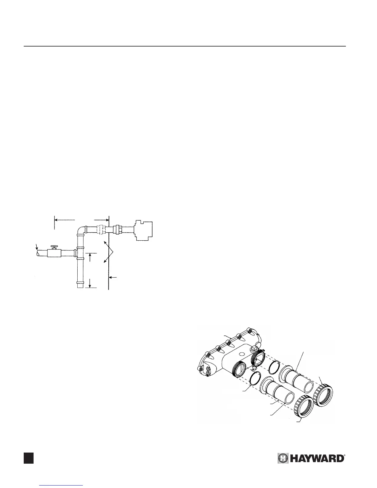
Figure 21: Sediment Trap
Figure 22: Pipe Nipple Installation
GAS
SUPPLY
GAS
VALVE
3” TYPICAL
SEDIMENT
TRAP
MANUAL
SHUT OFF
VALVE
6’ MAX.
UNION
HEATER CABINET
SUBJECT TO
LOCAL CODES
FRONT HEADER
O-RINGS
UNION NUTS
INLET - TOWARDS
FRONT OF HEATER
FLANGE PIPE
NIPPLES
OUTLET - TOWARDS
BACK OF HEATER
TURN CLOCKWISE
TO TIGHTEN. HAND
TIGHTEN ONLY.
 Loading...