EasyManuals Logo
Home>Hayward>Lighting Equipment>ProLogic

Hayward ProLogic Troubleshoot Manual

Hayward ProLogic
50 pages
To Next Page IconTo Next Page
To Previous Page IconTo Previous Page
Page #5 background imageLoading...
Page #5 background image
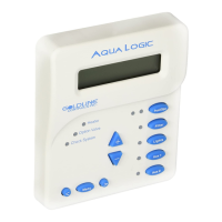
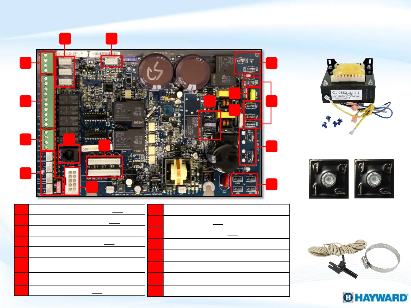
ProLogic: Main PCB Layout
A
Remote
DSP comm (RS485 10VDC)
B
Temp sensor terminal block (5
VDC)
C
Heater
1&2 terminal block (dry contacts)
D
Valves 1
-4 & 4Amp fuse ( 24VAC)
E
Cell
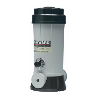
Plug for chlorination
F
High
Voltage Relays (top Filter, Lights,
AUX1, AUX2; bottom (AUX 3
-6).
G
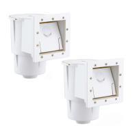
Flow Monitor (flow switch connector)
H
Transformer Input (120
VAC X 2)
I
System
Input Power (120VAC from breaker)
J
Rectifier input (24
VAC for Chlor. circuit)
K
Transformer
Output (24VAC)
L
20Amp Fuse (protects
Chlor. circuit)
M
Rectifier Output
(18-33VDC Chlor. circuit)
N
Sense & Dispense
output (120VAC)
O
Local
Display power (11VDC)
P
Plugs for accessory equipment (11
VDC)
I
G
J
Transformer
Rectifiers
Air/Water Sensor
M
H
K
L
N
F
E
D
C
B
A
P O

Questions and Answers:

Question and Answer IconNeed help?

Do you have a question about the Hayward ProLogic and is the answer not in the manual?

Hayward ProLogic Specifications

General IconGeneral
BrandHayward
ModelProLogic
CategoryLighting Equipment
LanguageEnglish

Related product manuals