DR. JOHANNES HElDENHAlN GmbH
D-8225 Traunreut ‘Tel. (08669) 31-O
SERVICE MANUAL TNC 151/155
Page 15
Kundendienst
Section 2.2.4
2.2.4 Testing of the Power Supply Unit
The procedure for testing the Power Supply Unit is shown in
the flow diagram on page 16.
As part of that procedure, it
may be necessary to test the voltages at various points on
The Power Supply Board under load.
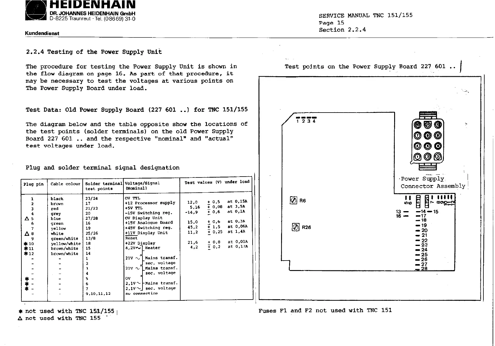
Test Data: Old Power Supply Board (227 601 ..I for TNC 151/155
The diagram below and the table opposite show the locations of
the test points (solder terminals) on the old Power Supply
Board 227 601 . .
and the respective "nominal" and "actual"
test voltages under load.
Plug and solder terminal signal designation
Test points on the Power Supply Board 227 601 . .
I
'Power supply.
~1
Connector Assembly!
._
-ii,
-19
- 20
- 21
1,‘:
-24
-25
*not used with TNC lSl/lSS~
A not used with TNC 155 I
Fuses Fl and F2 not used with TNC 151

 Loading...


