- 8 -
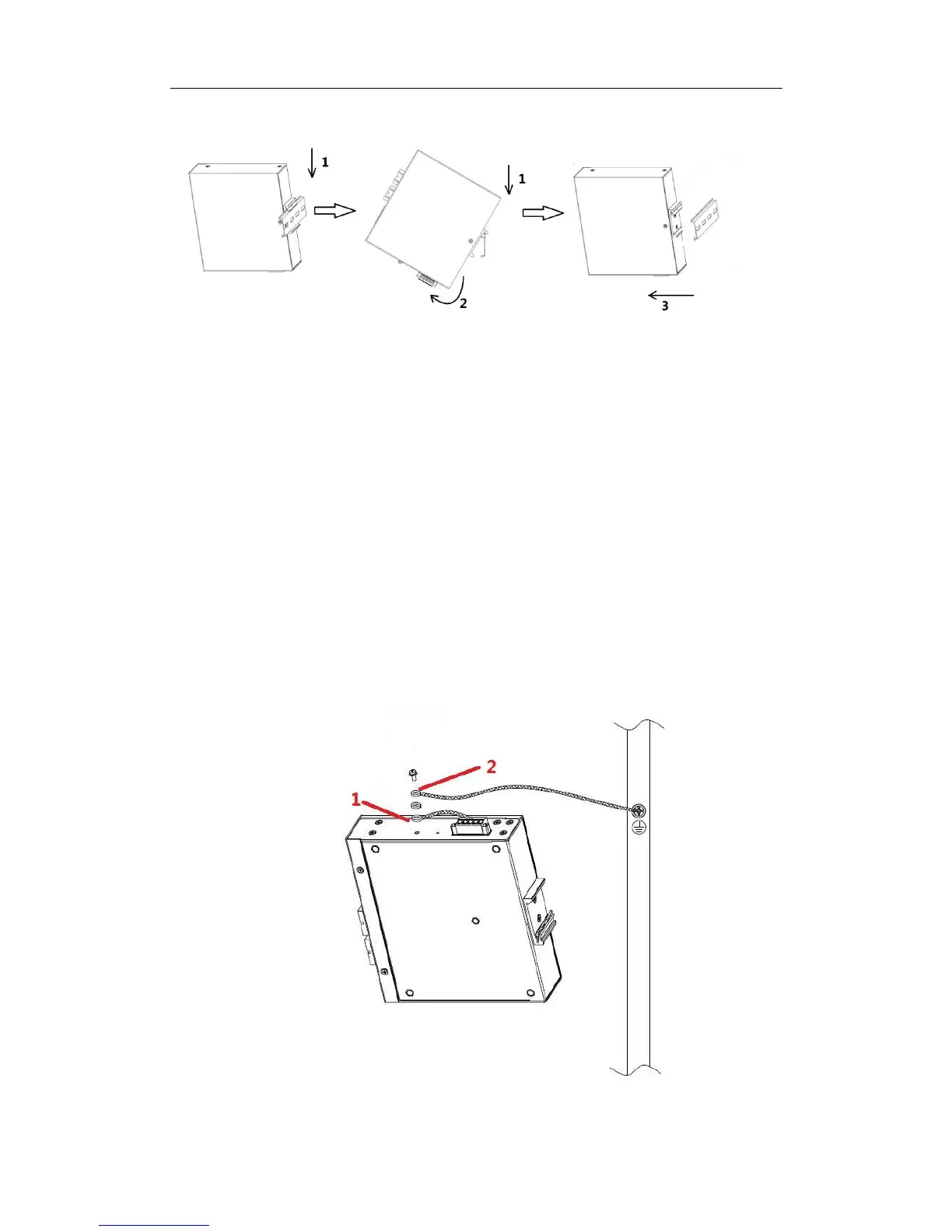
Figure 3-2 track installation diagram
3.3 connection protected ground line
Connecting the ground wire is not only to release the overvoltage and overcurrent caused
by lightning stroke as soon as possible, but also a necessary measure to ensure personal
safety.
The side panel of the industrial switchboard provides a grounding bolt, which is an
important guarantee for the equipment to prevent thunder and prevent interference, so the
user must be grounded correctly. The GND pin on the power supply terminal has been
connected to the ground screw and grounded before power up. As shown in the figure below,
unscrew the combined screws on the housing.
the line that is drawn from the GND foot on the power terminal.
is the grounding wire, one end of which is placed on the gasket after the cold
pressure terminal is pressed. According to the order shown below, the earth
screws are fixed on the "shell ground" with the grounding screws, and the other
end is reliably connected to the earth. When the power is broken, the grounding
wire is broken. The applicable power line diameter is 10AWG; the applicable
fastening torque is 5NM~6NM; please use the stainless steel M4 nut to lock.

 Loading...