EasyManuals Logo
Home>HIKVISION>Intercom System>8 Series

HIKVISION 8 Series User Manual

HIKVISION 8 Series
25 pages
To Next Page IconTo Next Page
To Previous Page IconTo Previous Page
Page #15 background imageLoading...
Page #15 background image
- 10 -
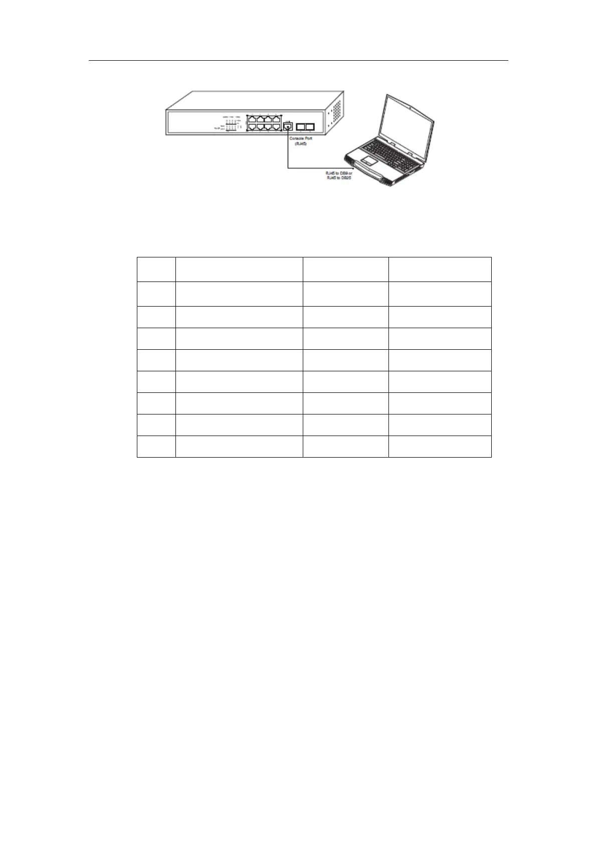
Figure 3-4 Connecting the console port of 8/24 and computer
Table 3-1 Definition of the pins of the console port
No.
Name
Abbreviation
Remarks
1
Carrier Detecting
CD
No connect
2
Data receiving
RXD
Input
3
Data-line device ready
DSR
No connect
4
Data transmitting
TXD
Output
5
Transmission requesting
RTS
No connect
6
Response transmitting
CTS
No connect
7
Data terminal ready
DTR
No connect
8
Signal ground
SG
GND
Note:
Because the console port of 8/24 switch bears no flow control, you need to set
Data flow control to none when using a superior terminal to manage 8/24 switch
configurations, or the single-pass problem will arise from the superior terminal.
The cable is used to connect the console port of the 8/24 switch and the outside
console terminal device. One end of the cable is a 8-pin RJ45 plug and the other
end is a 25-hole plug (DB25) and a 9-hole plug (DB9). The RJ45 plug is put into
the socket of the console port on the 8/24 switch. DB25 or DB9 is applied
according to the requirement of the terminal serial port. The inner line connection
in the cable is shown in Figure 3-5.

Questions and Answers:

Question and Answer IconNeed help?

Do you have a question about the HIKVISION 8 Series and is the answer not in the manual?

HIKVISION 8 Series Specifications

General IconGeneral
BrandHIKVISION
Model8 Series
CategoryIntercom System
LanguageEnglish

Related product manuals