- 11 -
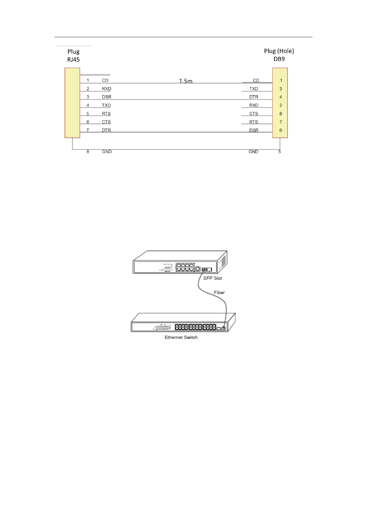
Figure 3-5 Cable connection at the console port
3.3.2 Connecting the SFP Ports
8/24 switch provides 2/4 gigabit SFP optical ports. Each port corresponds to one indicator
respectively, which is used for indicating the port Link/ACT state. When the indicator is always
on, the link is normal; when it flickers, the data receives and forwards. To use the optical port,
you need connect it to the SFP optical module, and then to other Ethernet terminal devices
through an optical fiber.
Figure 3-6 Connecting the SFP ports and other Ethernet terminals
3.3.3 Connecting Gigabit Ethernet TX Ports
The 8/24 switch has 8/24 10/100/1000 Base-TX ports. Each port has one indicator, which
indicates the state of Link/ACT. If the indicator is always on, the port is linked up; if the indicator
flickers, the data is transmitted on the port. The numbering order of the pins in the UTP port is
the same as the console port.
 Loading...