Install Introduction
Back panel interface introduction
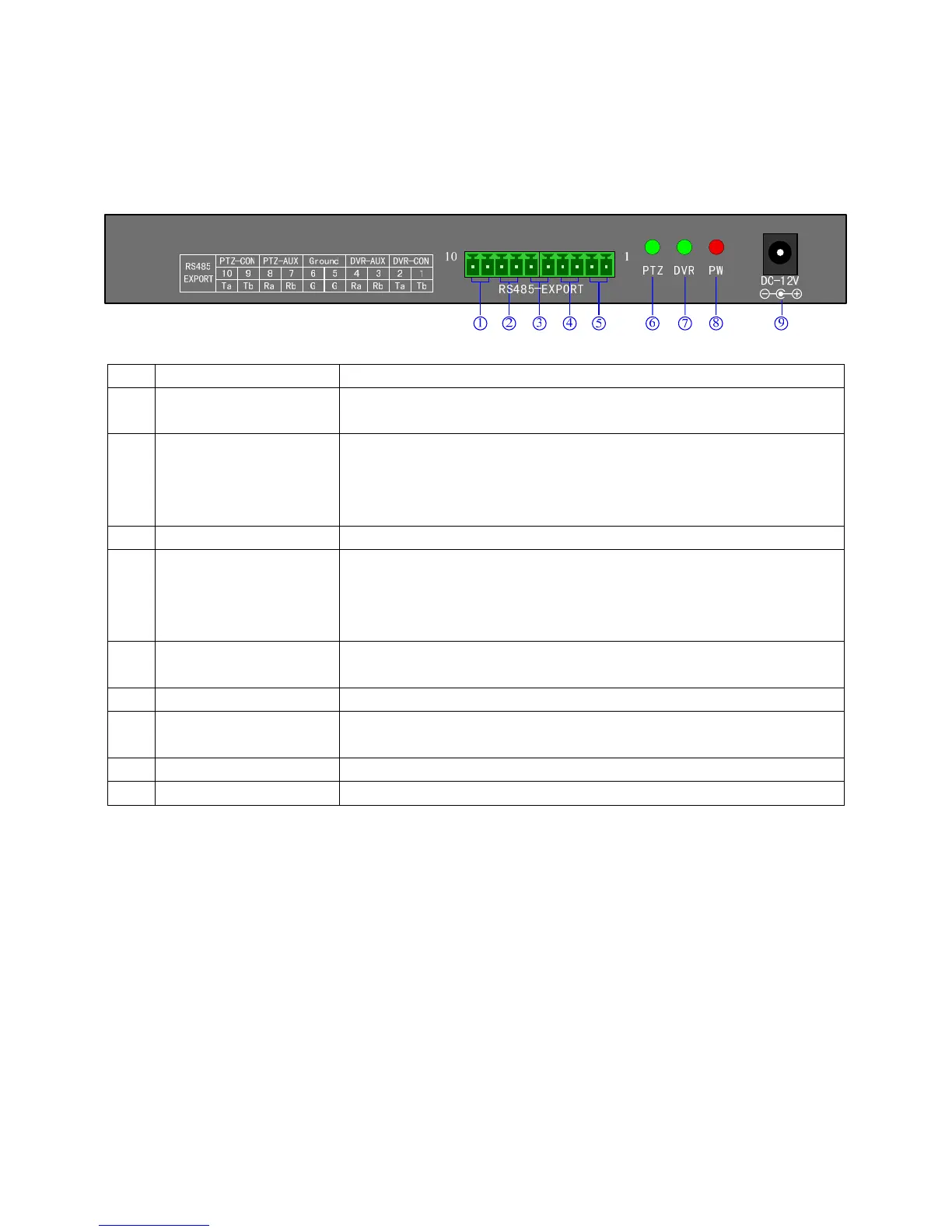
Introduction: DS-1002K、DS-1003K Back panel interfaces are the same
Fig 1
No
Physical interface Connect introduction
1
Output of control PTZ
PTZ-CON
Host keyboard connects PTZ RS485 port. Ta is for RS485+, and Tb is for
RS485-
2
Input of auxiliary keyboard
for PTZ control
PTZ-AUX
Host keyboard connects auxiliary keyboard for PTZ control. Host keyboard
pin8 (Ra) connects auxiliary keyboard pin10 (Ta), and host keyboard pin7
(Rb) connects auxiliary keyboard pin9 (Tb). Then auxiliary keyboard can
control PTZ.
3
Ground
Ground control signal line terminal
4
Input of auxiliary control
keyboard for DVR control
DVR-AUX
Host keyboard connects auxiliary keyboard for DVR control. Host keyboard
pin4 (Ra) connects auxiliary keyboard pin2 (Ta), and host keyboard pin3 (Rb)
connects auxiliary keyboard pin1 (Tb). Then auxiliary keyboard can control
DVR.
5
Output of control DVR
DVR-CON
connect host keyboard pin2 (Ta) with DVR KB port D+, and connect host
keyboard pin1 (Tb) with DVR KB port D-
6
PTZ control indicator light
In PTZ control mode, the led is green lighted and twinkling.
7
DVR control indicator
light
In DVR control mode, it is green and twinkling.
8
Power light PW
The lamp of keyboard is constantly red lighted on the working state
9
Power input DC-12V DC 12V power input
5
 Loading...