User Manual of Digital Video Recorder
29
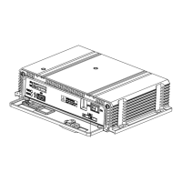
Connector for RS-485 devices. T+ and T- pins connect to R+ and R-
pins of PTZ receiver respectively.
D+, D- pin connects to Ta, Tb pin of controller. For cascading
devices, the first DVR’s D+, D- pin should be connected with the
D+, D- pin of the next DVR.
Connector for alarm input.
Connector for alarm output.
AC 100 ~ 240V power supply.
Switch for turning on/off the device.
BNC connector for audio input.
Connects external SATA HDD, CD/DVD-RW.
Connector for RS-232 devices.
 Loading...