24
Installation OS20/OS30
Release
03
06/2015
2.3 Wiring the connectors for supply voltage
and signal contact
The supply voltage and the signal contact are connected by means of a 5-pin
M12 connector.
See “Scope of delivery” on page 34.
Relevant for installations under UL conditions:
Use an UL approved power supply plug which is suitable for the voltage
range, the current and the ambient temperature range of this device, for
example the Lumberg RKC series. A pin assignment drawing of the power
supply connector is provided in table 4.
The supply voltage can be connected redundantly. Both inputs are
uncoupled. There is no distributed load. With redundant supply, the power
supply unit with the higher output voltage supplies the device on its own. The
supply voltage is electrically isolated from the housing.
Note: With non-redundant supply of the mains voltage, the device reports a
power failure. You can prevent this message by applying the supply voltage
via both inputs, or by changing the configuration in the Management.
Use a power supply cable which is suitable for the voltage, the current and
the physical load.
Hirschmann recommends a wire diameter of 0.5 mm² to 0.75 mm²
(AWG20 to AWG18).
Use a back-up fuse suitable for the supply network.
See “General technical data” on page 30.
Make sure that the disconnecting device is easily accessible for
disconnecting the device from the mains voltage.
Note: Connectors are not electrical isolating devices. Therefore, first plug the
connector into the power supply plug and then switch on the power supply.
Mount the connector for the supply voltage and the signal contact on the
front of the device.
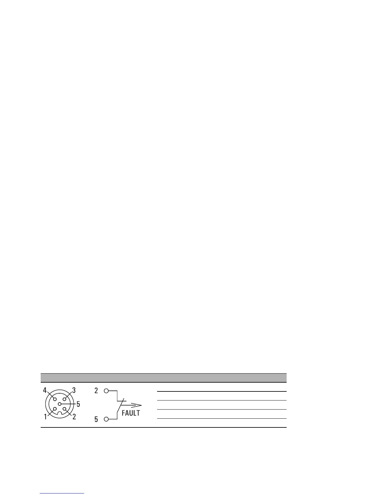
Figure Pin Function
1 + 24 V DC (1)
2Fault
30 V DC
4 + 24 V DC (2)
5Fault
Table 4: Pin assignment of the 5-pin M12 socket for connecting the 24V supply
voltage and the signal contact
 Loading...