9
AV3000 AVC Unit Service Manual
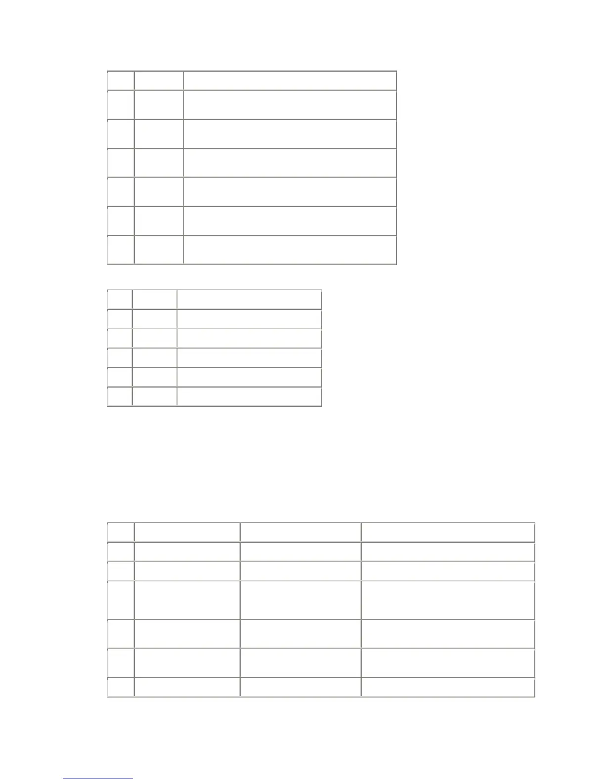
4.5.1.
Voltage Regulators
CRN Type
Remarks
I603 BA06T
Input +9.5V2 - Output +8V
For video chroma circuit (page 1)
IC602 SI-3050LSA
Input +5.5V1 - Output +5VFE
For tuner (page 1)
IC603 SI-3050LSA
Input +5.5V2 - Output +5V
For audio processor circuit (page 2), comb filter (page 6)
IC601 SI-3033LSA
Input +5VSTB - Output 3.3VSTB
For micro-controller circuit
Q602 TK11125M
Input +5VSTB - Output 2.5VSTB
For micro-controller circuit
IC604 BA09FP
Input +9.5V1 - Output +9V
For interface circuit (Sheet 3)
4.5.2. Level Shift for Control Buses
CRN Type
Remarks
Q607 BSS138 3WB-DATA to change from 3V3 to 5V
Q603 2SC2412K 3WB-CLOCK to invert with 5V range
Q604 2SC2412K FC-ENABLE to invert with 5V range
Q605 2SC2412K MSC-ENABLE to invert with 5V range
Q614 BSS138 1900TX to change from 3V3 to 5V
4.6. Micro-controller (Schematic Sheet 5)
SCL3v3 and SDA3v3 are converted for 5V operation in Q700, Q701, Q705 & Q706. OSD/TEXT RGB
at pin 58/59/60 are synchronised with progressive sync pulses 2H (32KHz) at pin 32 and V (50/60Hz)
at pin 33. RGB and BLK are also converted to 5V operation at Q713, Q714, Q715 and IC707. AV link
is bi-directional bus from pin 10 of SCT101 made by Q709/D701~D703. For the micro, input and
output are separated. The signal level is also converted between 3V3 in micro and 5V for SCART.
See 'Micro-controller Pinout' in the PINOUT DATA section of this manual for microcontroller pin functions.
(IC701B Option not fitted.)
CRN Type Description Remarks
IC704 SDA5550 Micro-controller See below
X700 Crystal 6MHz
IC700 M24C16W EEPROM (16k-bits)
Supply voltage: +3.3VSTB at pin 8
Control by I
2
C: SDA3v3 at pin 5 and SCL3v3
at pin 6 and WC3v3 at pin 7
IC701 AT49LV002N
Flash memory (256Kbytes) for
software stored
Supply voltage: +3.3VSTB at pin 32
Control by address and data buses
IC703
K6T1008V2E-GB70000 or
equivalent
SRAM, SMT (128kbytes)
Supply voltage: +3.3VSTB at pin 32
Control by address and data buses
IC705 M62703SL/ML Reset IC for IC704 Supply voltage: +3.3VSTB at pin 1
 Loading...