12
AV3000 AVC Unit Service Manual
4.8.2.
26-way Connector
Connection with FC/MSC Board (PL700).
Assuming that 1
V
p-p
video signal with 75 ohm terminated is input through SCT100-BOTTOM (AV3):
• UV are inverted by Q609, Q612, Q610 & Q613 to CbCr (U'V') at pin 25/24 and those are
adjusted to the level at 1.4Vp-p
• Y is amplified by Q608/Q611 to adjust the level at 1.4V for signal and 0.6V for sync (2V
p-p
in
total) at pin 26
Sound level L and R at pins 6/4 should be 500mVrms on the condition that:
• 500mVrms audio is input through SCT100-BOTTOM (AV3)
• BG FM sound with 54% modulation is received
Connection with FC/MSC Board (PL701).
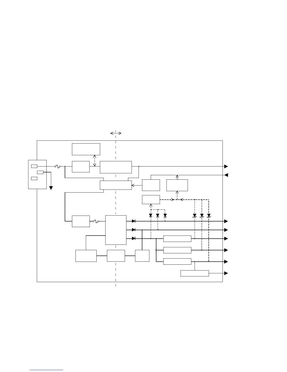
5. AVC POWER BOARD DESCRIPTIONV T
5.1. AVC Power Board Block Diagram
5.2.
Switching Regulator, Controller and Power MOS FET
STR-F6668B (I901).
Supply voltage at pin 4:
• Over +16V (start operating),
• over +10V (keep operating).
To Frame
GND
AC in
100~240V
Fuse F901
4A/250V
Relay
S901
Main
Rectifier
Standby
Rectifier
D902
D901
Standby
DC/DC
Converter
H901
Switching
Transformer
T901
Primary
Secondary
I932
DC/DC Converter
I931, D950, L931
STBY +5V
to AV Board
30V
to AV Board
9.5V
to AV Board
1.8V
to FC Unit
3.3V
to AV Board/FC Unit
5.5V
to AV Board/FC Unit
5V
to FC Unit
AC INLET
16V
Relay
Driver
Q930
Protection
Circuit
Q931, Q933
POWER on/off
from AV Board
(Detect
Voltage-down)
SW
Q932
Over-voltage
Protection
Circuit
R914, Q902~4
Switching
Regulator
I901
Photo-
coupler
I902
Error
Amp
Q934,
D938
(Detect
Voltage-over)
Fuse F902
2A/250V
I933, D949, L932
I930, D959, L933
DC/DC Converter
DC/DC Converter
DC/DC Converter
 Loading...