A TOUR OF THE SYSTEM
8
ABOUT THE SYSTEM
A
Tour of the System
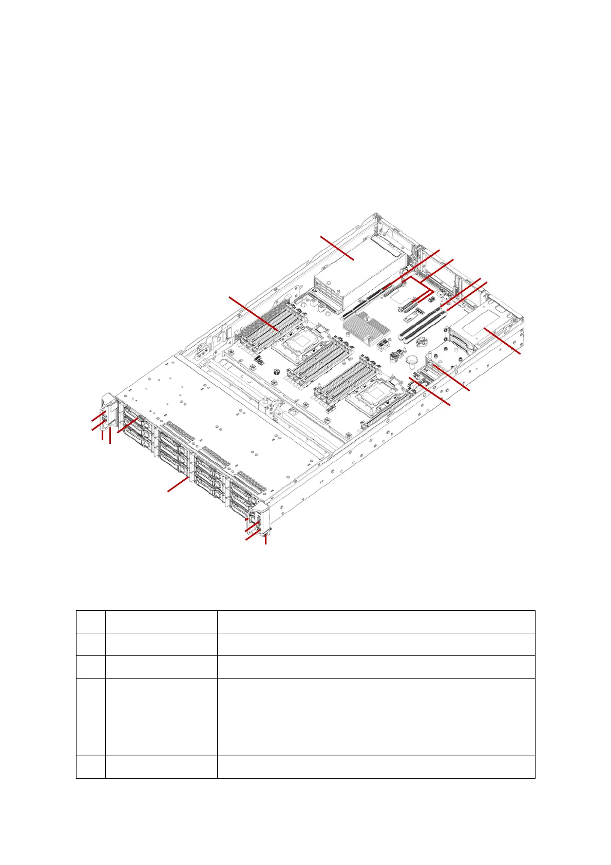
System Overview
The server is available as a 3.5” storage drive configuration.
The 3.5” storage drive configuration system overview is displayed in the following image:
Figure 1.
3.5” Storage Drive System Component Overview
Table 2: Component Overview
NO.ITEM DESCRIPTION
1 Front control panel
See Front Control Panel (FCP) on page 12
2 USB port Connect to USB device
3Handle
Two server handles used for pulling the system out of the rack
THE HANDLES ARE DESIGNED FOR THE EXTENSION OF THE SYSTEM FROM THE RACK.
T
HE HANDLES ARE NOT DESIGNED TO CARRY THE WEIGHT OF THE SYSTEM. DO NOT USE
THE HANDLES TO MOVE OR LIFT THE SYSTEM.
4 Thumb screw Secure the system to rack frame
11
8
9
14
15
13
1
7
2
16
2
5
3
3
6
4
4
10
12
 Loading...