-6-
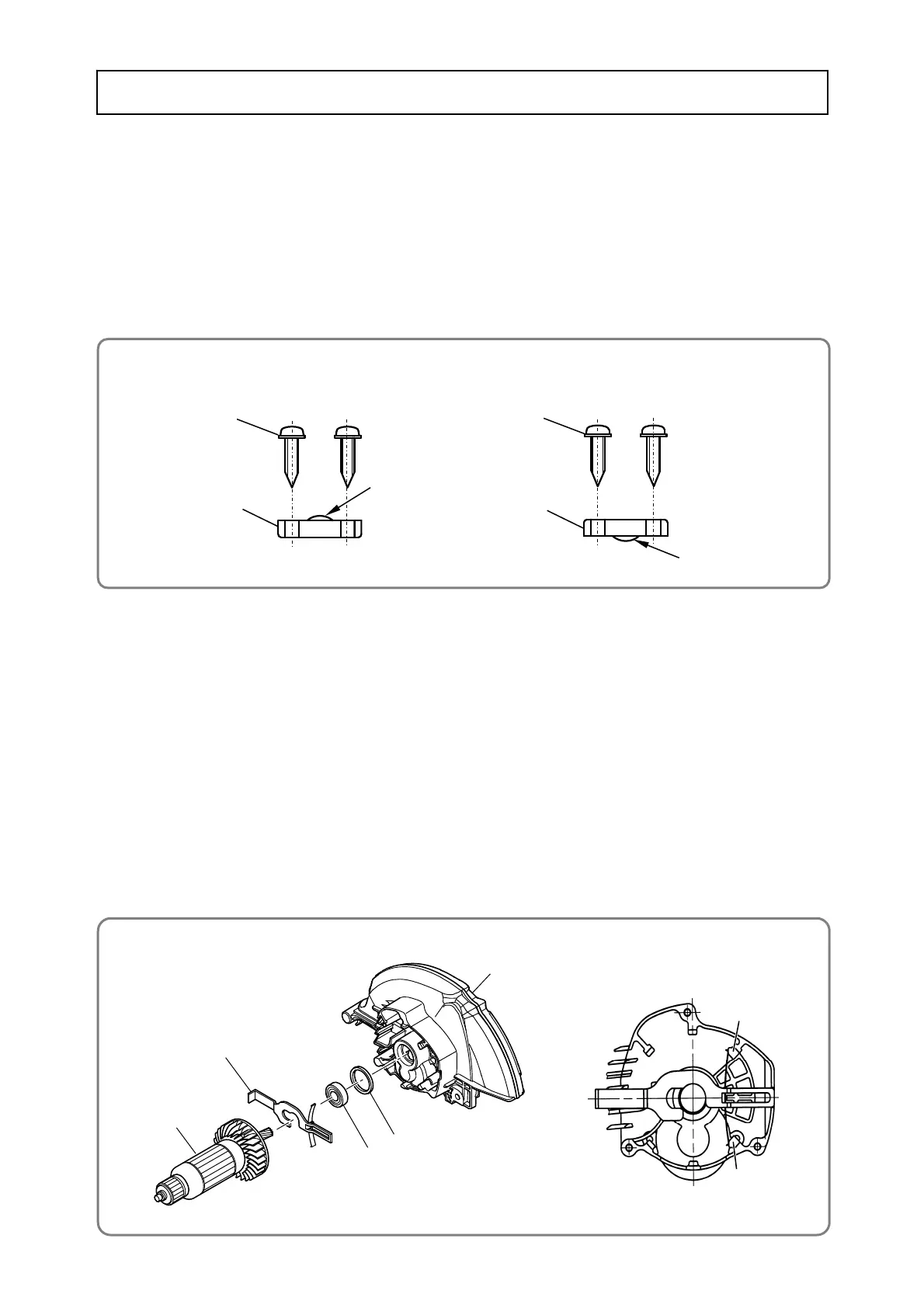
• Mounting the gear cover
[23]
[22]
[30]
[26]
Protrusion
[49]
[48]
Other than the USA, Canada, and Mexico
For the USA, Canada, and Mexico
[31]
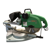
• Mounting the cord clip
Generally, perform reassembly by reversing the disassembly procedure. However, special attention should
be given to the following items. Refer to “Lubrication points and type of lubricant” on page 8 for the grease
required for reassembly.
1. Reassembly of the power supply unit and its vicinity
Perform wiring according to the wiring diagrams shown on page 10 when replacing the Stator Ass'y [20],
Cord [53], Noise Suppressor [35] or Switch [45]. Mount the Cord Clip [48] in the direction shown in the
following figure.
2. Mounting the stator ass'y
Press-fit the Stator Ass'y [20] into the Housing Ass'y [40] so that the internal wire of the Stator Ass'y [20] is
positioned to the opposite side of the name plate on the Housing Ass'y [40]. Refer to the wiring diagrams
on page 10. After press-fitting, hook the Brush Terminal [19] on the Brush Holder [41].
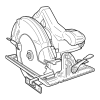
3. Mounting the gear cover
(1) Mount the Rubber Ring [31] into the Gear Cover [26]. Mount the Lock Lever [23] between the fan of the
Armature [22] and Ball Bearing 6001VV [30]. Then carefully mount it into the Gear Cover [26].
NOTE: Check that both ends of the flat spring on the Lock Lever [23] are properly supported
inside the ribs of the Gear Cover [26].
(2) After mounting the Lock Lever [23], check that the Gear Cover [26] is secured to the Housing Ass'y [40]
with the Machine Screws M5 x 50 [38]. Push the Lock Lever [23] by hand and check that it returns to its
original position when released.
Reassembly
Protrusion
[48]
[49]
Rib
Rib
 Loading...