ABOUT THE SYSTEM SYSTEM REAR VIEW
1-8
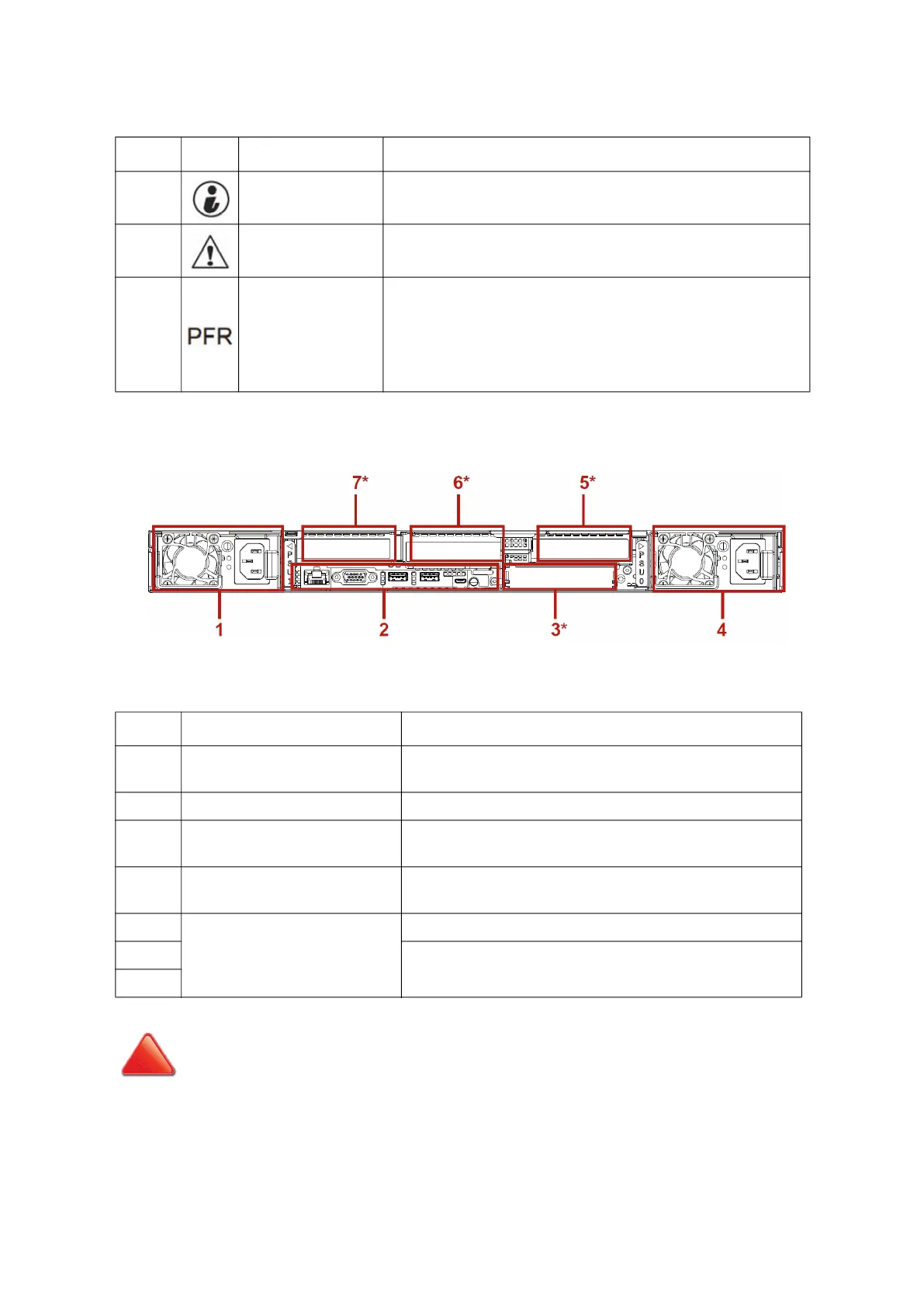
System Rear View
Figure 1-3. System Rear View
3.
Identification but-
ton with LED
Toggles ID LED, activate ID LED to identify system
Blue blinking – Identifier on front and rear chassis; off – Normal.
4. System Status LED
Provides critical and non-critical failure notification
Amber blinking – failed; Off – SEL cleared / good
5.
PFR Status LED
(Only for certain
models)
Provides notification of PFR operation status
Off: Power Off/PFR Module is not installed
Green On: Authenticated
Amber On: Failed
Amber Blinking: Authentication/Recovery is executing in T-1
Table 4: System Rear View
NO. FEATURE DESCRIPTION
1. Power sub-system
Main power supply unit (PSU1). See Power Sub-System on
page 1-9
2. System I/O ports See System Rear I/O on page 1-9
3. Expansion slot*
Support OCP 3.0 mezzanine card with adapter installation
(PCIe Gen4 x 8, CPU0)PCIe HHHL
4. Power sub-system
Main power supply unit (PSU0). See Power Sub-System on
page 1-9
5.
Expansion slot*
PCIe expansion slot with PCIe HHHL x 16 (CPU0)
6.
PCIe expansion slot with PCIe HHHL x 16 (CPU1)
7.
CAUTION!
*SOME ADD-ON CARDS MIGHT BE HOT AFTER SYSTEM POWER IS OFF. CONTACT SHOULD BE MADE WITH CARE.
Table 3: Front Control Panel Definition (Continued)
NO. ICON NAME DESCRIPTION