28
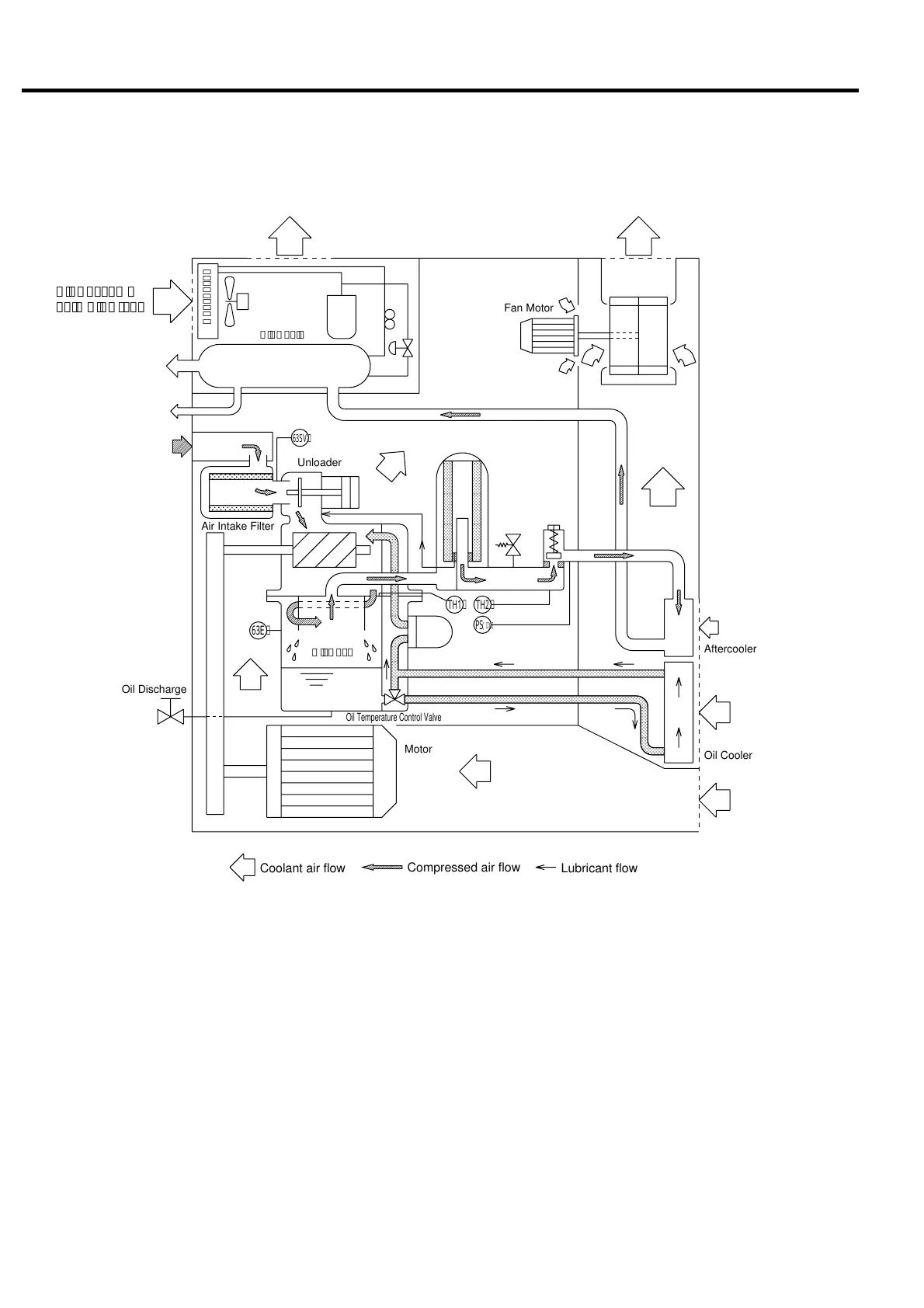
TH1 : Thermistor (discharge temp. 1)
TH2 : Thermistor (discharge temp. 2)
PS(1): A pressure sensor (for capacity control)
6. SYSTEM OF EACH COMPONENT
6.1 Compressed Air/Lubricant System
6.1.1 Compressed air flow
The air under atmospheric pressure is taken in
the unit through Air Intake Filter and is com-
pressed by a compressor to the specified pressure.
This Compressed Air flows in the Oil Case to-
gether with Lubricant, and by which Compressed
Air and Lubricant are separated. Segregated
Compressed Air is cooled in the Aftercooler and
then discharged out.
6.1.2 Lubricant flow
The Lubricant circulates in the unit by means of
pressure difference between the pressure in the
Oil Case and the one in the suction side of the
Compressor. The mixture of Compressed Air and
Heat Exchanged Lubricant are separated in the
Oil Separator into the Compressed Air and the
Lubricant. Segregated Lubricant is cooled in the
Oil Cooler afterwards and returns to the suction
side of Compressor, then it makes Heat Exchange
with another Compressed Air again.
63E : Pressure switch
63SV : Pressure differential sensor of air intake filter
;;;;;;;;;;;;;;;;;;;
;;;;;;;;;;;;;;;;;;;
;;;;;;;;;;;;;;;;;;;
;;;;;;;;;;;;;;;;;;;
;;;;;;;;;;;;;;;;;;
;;;;;;;;;;;;;;;;;;
;;;;;;;;;;;;;;;;;;
;;;;;;;;;;;;;;;;;;
;;;;;;;;;;;;;;;;;;
Lubricant flow
Compressed air flow
Coolant air flow
TH1
PS
(1)
TH2
63SV
63E
Oil Discharge
AirSucked
ontoAirDryer
Fan Motor
Motor
OilCase
Unloader
Oil Temperature Control Valve
Air Intake Filter
Oil Cooler
Aftercooler
Condenser
AirCooler
CoolingFan
Refrigerant
Compressor
Cooling Fan
Oil Separator
Oil Filter
Relief
Valve
AirExhaustedfromAirDryer AirExhaustedfromAirCompressor
AirSuckedonto
Aftercooler
AirSuckedonto
OilCooler
AirSuckedonto
Motor
CompressedAir
Discharged
Condensate
Drained
AirSuckedinto
AirEnd
Minimum
Pressure/
Check Valve
Compressor
 Loading...