4
Air discharge
Intake air
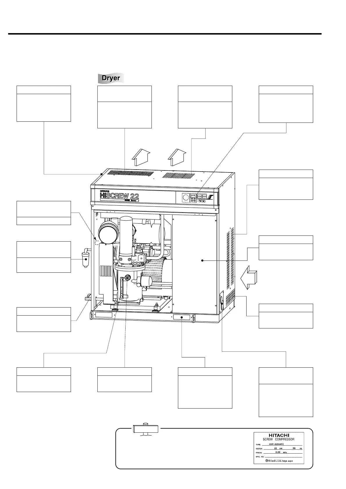
2. PARTS DESCRIPTION AND THEIR FUNCTIONS
2.1 Appearance
Cooling Air Inlet 1
To suck the ventilating
air for the oil cooler and
aftercooler.
Enclosure
To lower the noise,
sound absorbing mate-
rial is fixed to the inner
surface of the cover.
Instrument Panel
To mount instruments
and switches for the op-
eration (See “3. HOW TO
OPERATE” provision).
Fork Slot
To be used when carry-
ing and installing the
unit. Put the attached
noise-proof covers on
them after installation.
Starter
To be located under the
front door.
Oil Filling Port
To be used when filling
oil into the oil case.
Power Cable Conduit Hole
and External Wiring Port
Be sure to connect the
power cable with care
for the power source
electricity specification
(voltage and frequency).
Discharge Air Outlet
(left hand side)
Compressed air outlet.
A nameplate is attached on the right enclosure panel. It
indicates the A type (model number), motor out-
put and frequency, working pressure, and manufacturing
number. Inform the Hitachi distributor of such information
whenever asking it to service your A.
IMPORTANT
Cooling Air Outlet
(from air dryer)
To discharge the ventilat-
ing air that has been heat-
exchanged by the con-
denser.
Cooling Air Outlet
(from air compressor)
To discharge the ventilat-
ing air that has been heat-
exchanged by the oil
cooler and aftercooler.
Oil Level Gauge
To indicate oil level in
the oil case.
Cooling Air Inlet 2
To suck the ventilating
air for the motor.
Oil Draining Port
To be used when drain-
ing oil from the oil case.
Automatic
Condensate Trap
To automatically drain the
separated condensate.
Note: This illustrates the model with a built-in air dryer.
 Loading...