SJ300 Inverter
Operations
and Monitoring
4–59
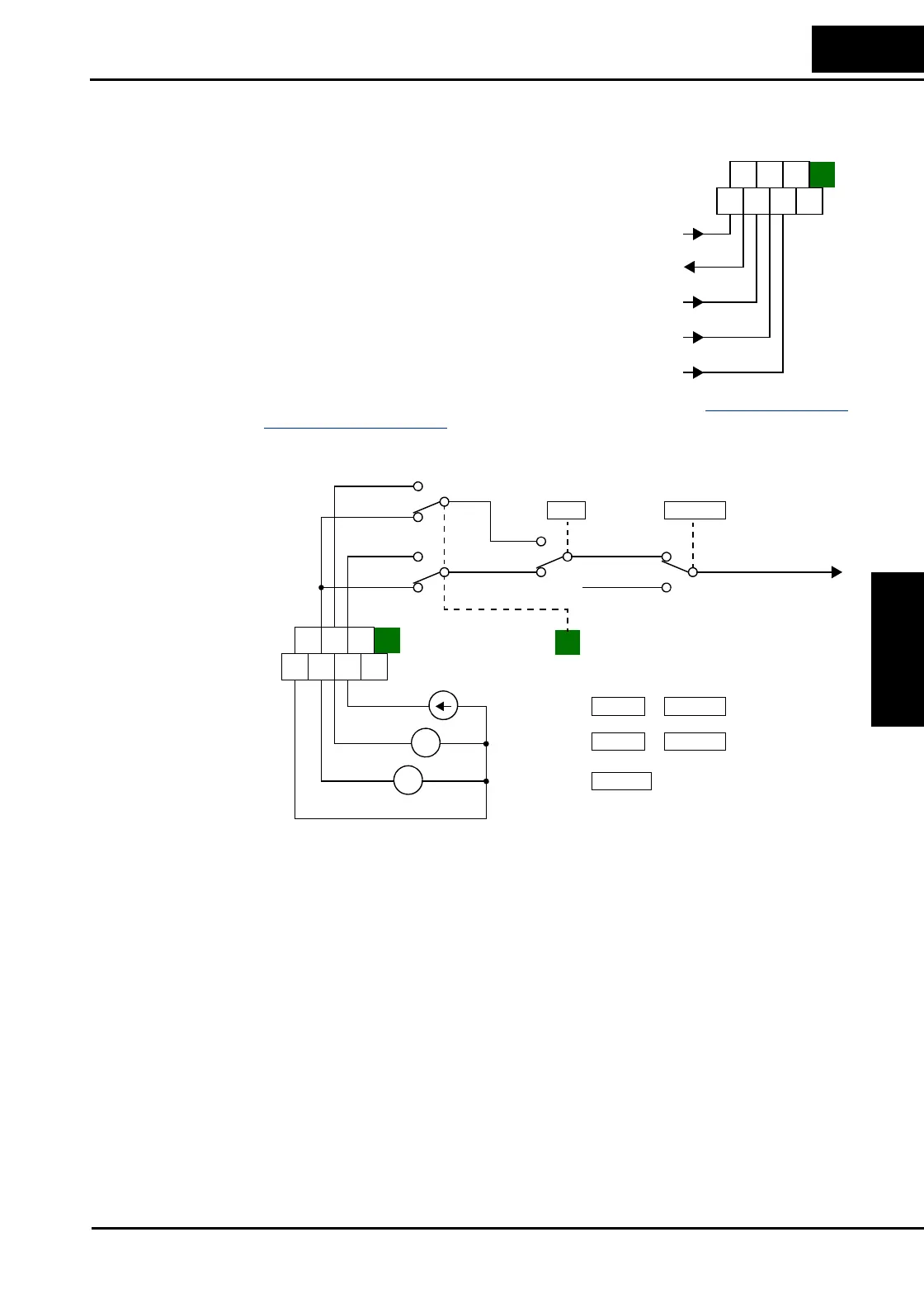
Analog Input Operation
Input Terminal
Signals
The SJ300 inverters provide for an external analog
input to command the inverter frequency output
value. The analog input terminal group includes
the [L], [OI], [O], [O2], and [H] terminals on the
control connector, which provide for Voltage [O]
and [O2] or Current [OI] input. All analog input
signals must use the analog ground [L].
If you use either the voltage or current analog
input, you must select one of them using the logic
input terminal function [AT] analog type. If
terminal [AT] is OFF, the voltage input [O] can
command the inverter output frequency. If terminal
[AT] is ON, the current input [OI] can command
the inverter output frequency. The [AT] terminal function is covered in “
Analog Input Current/
Voltage Select” on page 4–26. Remember that you must also set A001 = 01 to select analog
input as the frequency source.
Input Filter Parameter A016 adjusts an analog input sampling filter that evenly affects all analog inputs
shown above. The parameter range is from 1 to 30. Before increasing the filter setting, we
recommend trying to find the cause of input analog noise. Check for the following:
• Look for nearby high-current wiring—avoid any parallel runs to the analog signal wires
• Check the impedance between the chassis grounds of the inverter and the analog signal
source equipment—a good connection will have a low impedance
• Check the analog signal ground impedance from the inverter to the analog signal source
• Avoid ground loops... measure the current (or voltage drop) on the chassis ground and signal
ground connections; the ideal value is zero
After taking steps to minimize the analog signal noise sources, increase the filter time constant
(A016) until the motor output frequency (when commanded by analog inputs) becomes stable.
H O2
FM
AM
O OIL
AMI
+V Ref.
A GND
0—10V input
4—20mA input
-10 / 0 / +10V
+ –
4-20 mA
Frequency
source setting
1
V – I select
0 – 10V
+ –
-10 / 0 / +10V
O2
O
O
OI
H O2
FM
AM
O OIL
AMI
A005 A001=01
A005=00
A005=01
AT =ON
AT =OFF
AT =ON
0
1
0
1
0
1
0
1
Frequency setting
Terminals
(Keypad)
OI
O2
O
L
AT
 Loading...