CLCM1H,6H,6T DIGITAL WALL MODULES – INSTALLATION INSTRUCTIONS
MU1Z-0902GE51 R0416C 2
Wiring / Power
Wiring with PANTHER
NOTE: You should always first connect the DWM and only
then install the PANTHER's software.
Wire the terminal blocks as follows:
1. Strip 5 mm of insulation from the conductor.
2. Insert the wire in the required terminal location and
tighten the screw to complete the termination.
3. Verify that the DWM is wired according to Table 2.
Table 2. Terminal connections (PANTHER)
LED input (min. 5 Vdc, I ≤ 3 mA)
24 Vac/dc from controller, I
MAX
6 mA, with a valid range of 18 V (I
MAX
2.4 mA) to 27 V (I
MAX
10 mA)
When all wiring is complete, re-attach the cover of the DWM
as shown in Fig. 1.
NOTE: For specific wiring requirements, see section "Power
when Wired with PANTHER".
Power when Wired with PANTHER
CAUTION
Low-Voltage Equipment. Risk of equipment
damage.
If the DWM is powered by an external 24 Vac power
source, that power source must conform to Class II
restrictions. Thus, transformers must not be larger
than 100 VA. A transformer that is CE certified and
meets the Low Voltage Device (LVD) requirements
must be used in Europe for all installations of this
product.
If powered with 24 Vac, the DWM has a power consumption
of 0.2 VA.
The DWM does not require a dedicated transformer.
When hardwired with the PANTHER, the DWM can be
powered either
with 24 Vac/dc from PANTHER terminal 2 (via DWM
terminal 8; use min. 1.0 … 1.5 mm
2
wire) or
with 18…27 Vac/dc from PANTHER terminal 32 (via
DWM terminal 8).
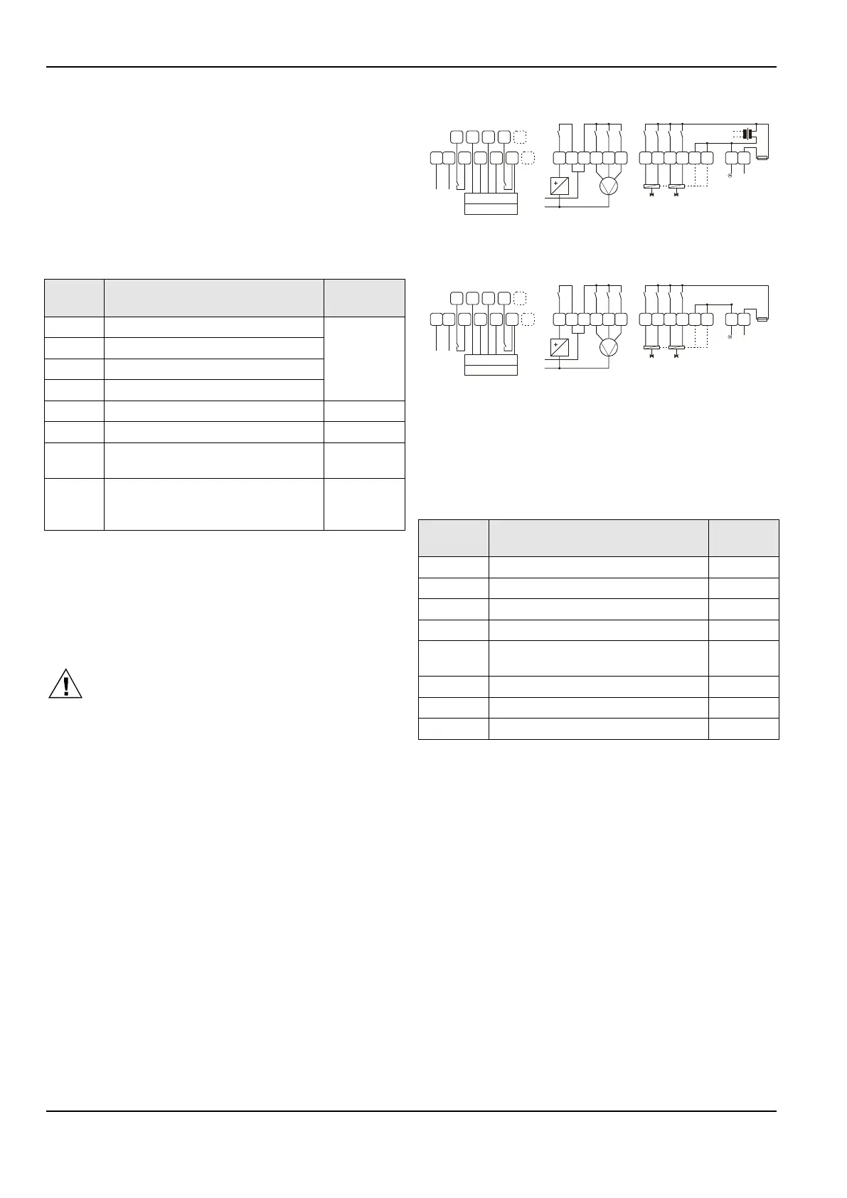
Wiring with SERVAL (CLCM6T21N, only)
LON
3
21 4
5
6 23
24
7
8
GND
9
LED
10
FAN
11
DI2
12
DI1
SET
SENS
GND
T7460 / T7560
5
3
4
2 1
triac
0.5 A
F2.5H
3A10A
13
14
15 18
17
16
III II I
L
N
230 V
fan
1920
2122
close
open
close
open
com
com
2526
OUT1 OUT2
230 Vac
~ ~
230 V
Fig. 3. Wiring of CLSE1L230
LON
3
21 4
5
6 23
24
7
8
GND
9
LED
10
FAN
11
DI2
12
DI1
SET
SENS
GND
T7460 / T7560
5
3
4
2 1
triac
0.5 A
F2.5H
3A10A
13
14
15 18
17
16
III II I
L
N
24 V
fan
1920
2122
close
open
close
open
com
com
2526
OUT1 OUT2
24 Vdc
~ ~
24 V
Fig. 4. Wiring of CLSE1L24
Wire the terminal blocks as follows:
1. Strip 5 mm of insulation from the conductor.
2. Insert the wire in the required terminal location and
tighten the screw to complete the termination.
3. Verify that the DWM is wired according to Table 3.
Table 3. Terminal connections (SERVAL)
LED input, 5 Vdc (I
MAX
= 3 mA) to
15 Vdc (I
MAX
= 4 mA)
When all wiring is complete, re-attach the cover of the DWM
as shown in Fig. 1.
NOTE: For specific wiring requirements, see section "Power
when Wired with SERVAL (CLCM6T21N, only)".
Power when Wired with SERVAL (CLCM6T21N, only)
When hardwired with the SERVAL, the CLCM6T21N must
not be powered by an external power source. Rather, it must
be powered with 5 Vdc (I
MAX
= 3 mA) to 15 Vdc (I
MAX
= 4 mA)
obtained only from SERVAL terminal 9 (via DWM
terminal 5).
 Loading...