INSTALLATION
3 EN1B-0022 IE10 R0717
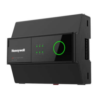
thus rotate CW until the mechanical end limits are
reached.
Figure 2 Setting the mechanical end limits
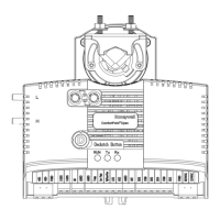
Mounting CPO-VAV2A on VAV box
electronics enclosure
Figure 3 Paste the drilling template in VAV box electronics enclosure
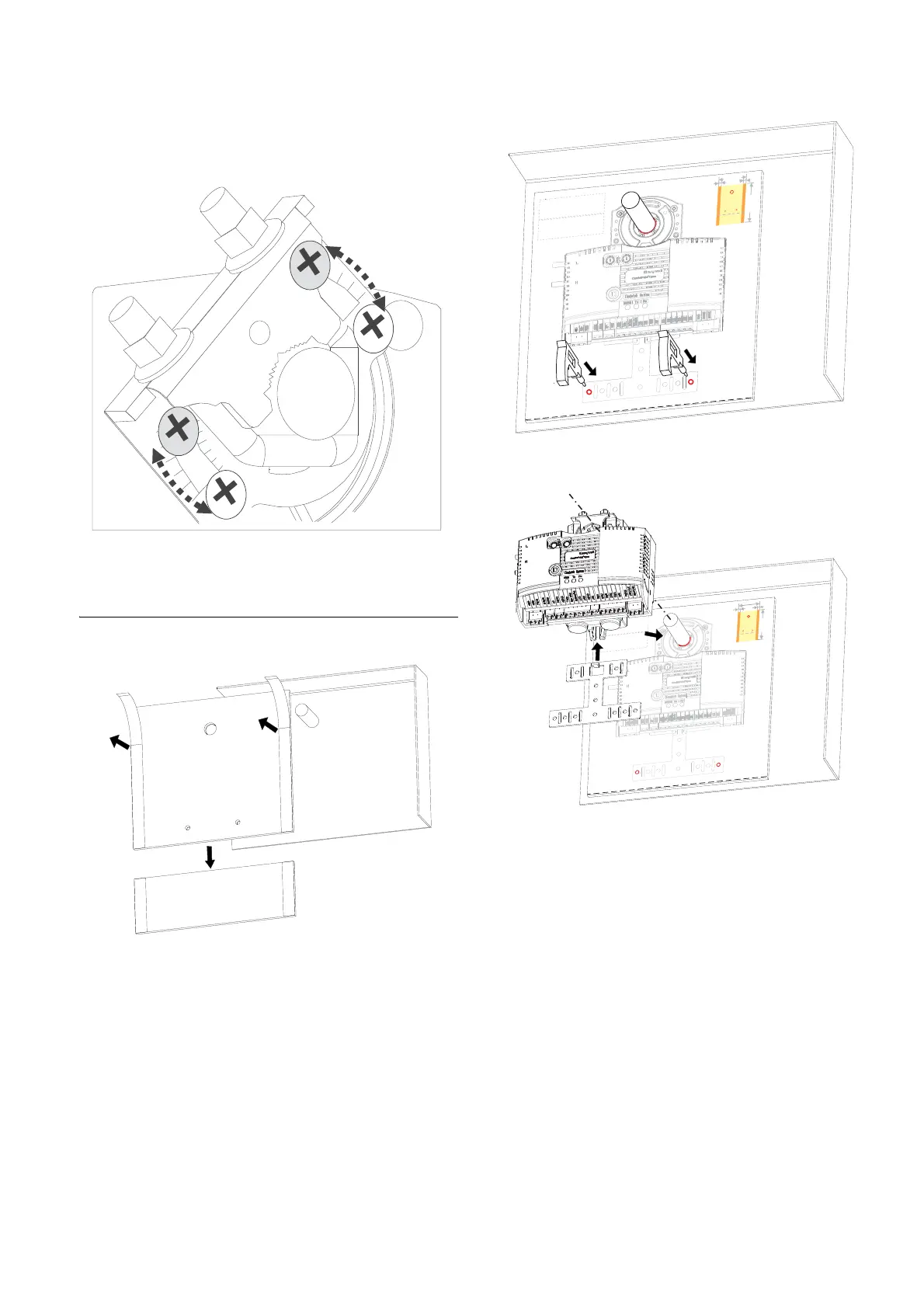
Figure 4 Drilling 2 holes per template indication
Figure 5 Attach controller on damper shaft and fix with anti-rotation bracket
1
2
For S
erial No. Label
For Safety Caution
Back view
30 mm
30 mm
210 mm
297 mm
F
o
r S
erial No. Label
2
1
Back view
30
m
m
3
0
m
m
21
0
m
m
297 m
m
 Loading...