DTC 100/4 TD
5
VDR resistor
Thermo-shrinkable
tubes
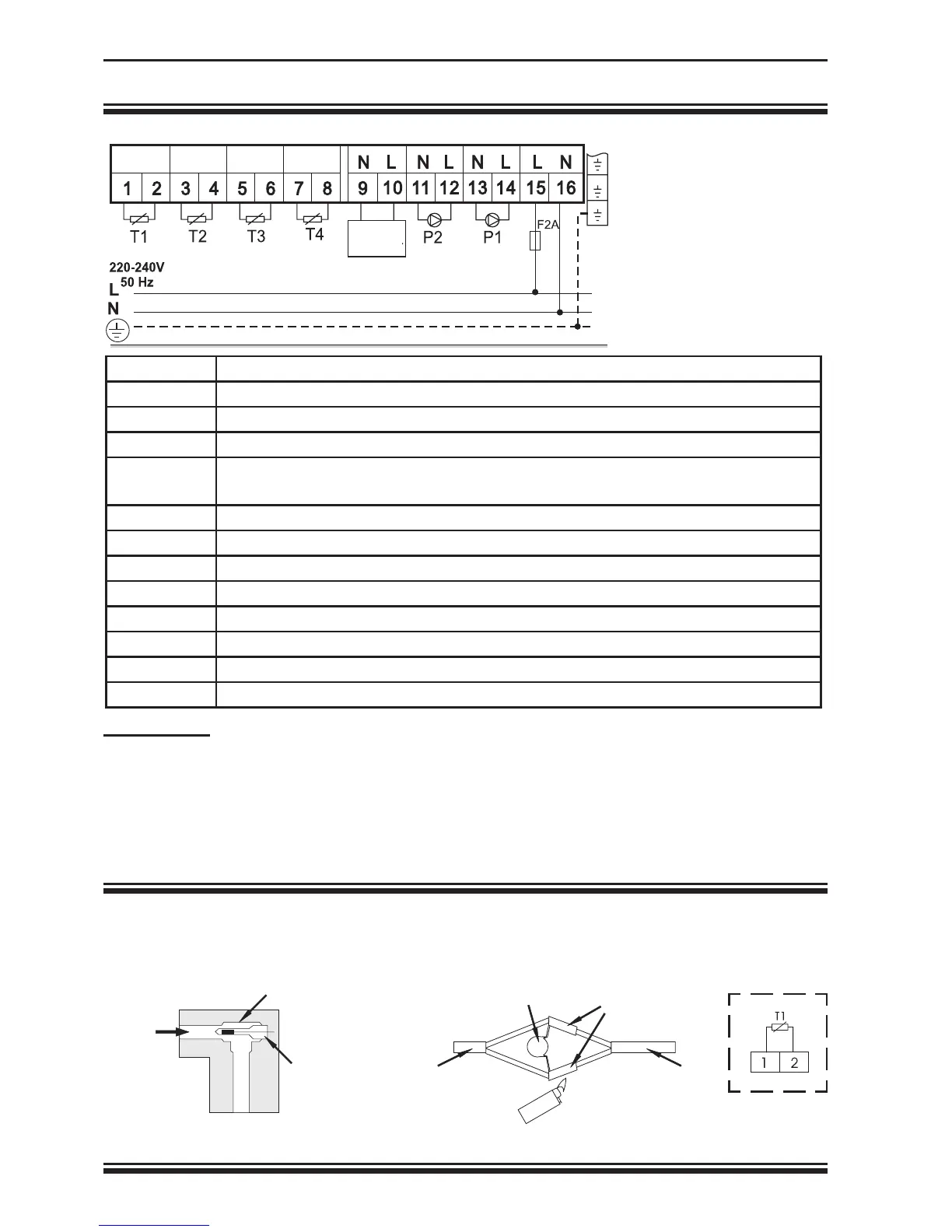
ELECTRIC CONNECTION:
Grounding wires
should be connected
to special terminal
pins situated on right
side of terminal strips.
WARNING:
Boiler control should be performed behind the main switch for burner but in front of boiler
thermostat. Care must be taken that differential thermostat and boiler connection are
performed at the same phase otherwise inter-phase contact can occur.
SENSOR INSTALLATION IN COLLECTOR:
Install it as immersion sensor in
collecting pipe at the top of the
collectors in provided sleeve
For cables longer than 15m we
recommend over-voltage protection
with VDR resistor.
flow
direction
T piece 1/2”
pipe 1/2”
extension
conductor
sensor conductor
Connection
to terminal pins
BOILER
TERMINAL CONNECTION
1,2 T1 sensor – heating source sensor (collectors, boiler…)
3,4 T2 sensor – hot water tank sensor
5,6 T3 sensor – heating source sensor for higher heating circuit (boiler)
7,8 T4 sensor – hot water tank sensor in upper part of hot water tank
neutral conductor
9 neutral conductor
10 phase for boiler (burner) switching on
11
neutral conductor
12 phase of pump for secondary heating circuit
13 neutral conductor
14 phase of pump for collector heating circuit
15 phase connector for mains 230V, 50 Hz
16 neutral conductor - connector for mains 230 V, 50 Hz
 Loading...