Electrical installation
Installation guide 762 VITO interfaces & VITO probes Page 19
The shielding must be connected to ground at both ends of the cable.
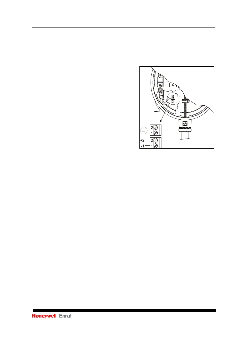
3.2.2 Supply / data communication connection for 361 VITO MPT probe, 76x
VITO probes and MRT
Refer to figure 9.
Remove the cover from the VITO
Interface enclosure (if not already
removed);
Remove the black plastic shield from
the VITO Interface converter block;
Insert the gauge wire into the cable
gland on the left hand side of the VITO
Interface enclosure;
Connect the twisted pair of gauge wire
to the terminals on the lower left hand
side of the converter block:
pin 1: -
pin 2: +;
Re-install the black plastic shield.
Figure 9 Connection of twisted pair
For gauge wiring
3.2.3 Supply / data communication connection for 365 VITO MPT probe
When a 365 MPT temperature and water probe is used, the VITO Interface contains two
modules. One for the spot temperature elements (at the front) and one for the capacitive
water probe (at the rear).
Both modules need to be connected with a separate supply / data communication cable.
Refer to figure 10.
Remove the cover from the VITO Interface enclosure (if not already removed);
Remove the black plastic shield from the VITO Interface converter block (1);
Disconnect yellow/green ground wire (3);
Remove front (temperature) module by loosening the two hex screws marked
(2) and store at a safe place;
Insert the gauge wire into the cable gland on the left hand side of the VITO
Interface enclosure;
Connect one twisted pair of the gauge wire to the terminals on the lower left
hand side of the rear (water) converter block:
pin 1: -
pin 2: +;
Re-install the black plastic shield on the rear converter block;
Remove dummy capacitor (refer to figure 11);
Connect the Coax cable and ground wire from the water probe (refer to figure
12: Water probe connections);
Re-install the front (temperature) module, including yellow/green ground wire;
 Loading...
