12 HPFF12 NAC Expander — P/N 53576:B 11/24/2010
System Overview Jumpers
1.4 Jumpers
The HPFF power supplies are comprised internally of two basic components: a 24 VDC power
supply and a Control circuit board. The HPFF12 models have an installed 12.0 A power supply.
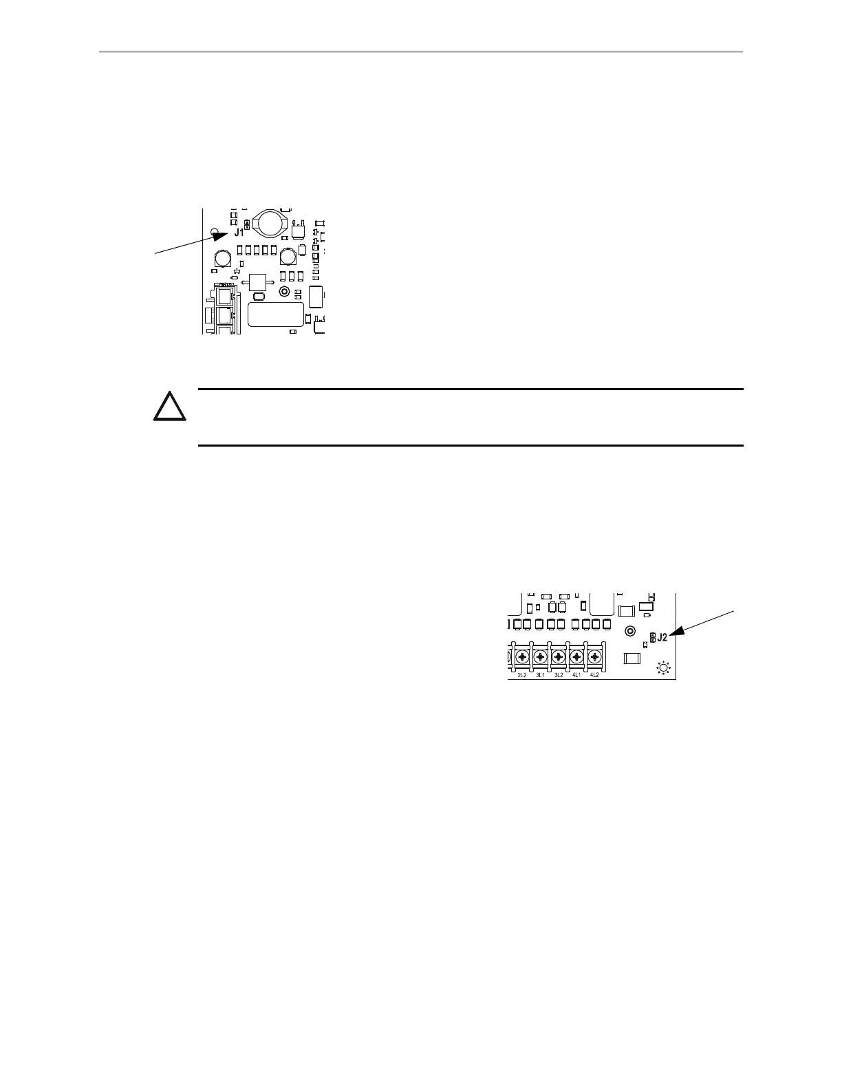
Jumpers are located on the control circuit board; see Figure 1.1, “Control Circuit Board”.
1.4.1 Charger Disable Jumper (J1)
The HPFF power supplies’ battery charger capacity is 26 AH maximum
using the integral charger with a maximum charging rate of 0.75 A. The
integral charger on the Control circuit board must be disabled in certain
situations by removing the charger-disable jumper. One situation is when
system requires a common battery set, as is possible in the large
equipment enclosure. Another situation is if the system requires a larger
battery capacity than the integral charger can charge in the proper time.
Larger capacity batteries can be used if they are housed in an external
UL-Listed enclosure, along with a UL-Listed battery charger that can
restore the full charge to the batteries in the proper time.
Larger capacity batteries can be used if they are housed in an external UL-Listed enclosure, along
with a UL-Listed battery charger suitable for fire alarm service and with sufficient capacity to
restore the full charge in the required time. The alternate enclosure and battery charger shall be
listed for Fire Protective Signaling use.
1.4.2 Ground Fault Disable Jumper (J2)
The Ground Fault detection circuit on the Control
circuit board monitors the impedance from earth
ground to any user wiring point, including +24 VDC.
An exception is the initiating device signal inputs
because they are optically-isolated from the rest of the
circuitry and should be detected by the initiating
device or FACP. Remove ground-fault disable jumper
to disable the ground fault detection.
If the common circuitry of two or more HPFFs are connected together, or if the common of an
HPFF is connected to the common of a system, such as a single battery connected to multiple units,
then the ground fault jumpers must be removed from all but one of the units. The unit with the
jumper installed provides the ground monitoring for the whole system. If two or more units are
connected together with ground fault monitoring enabled, then the monitoring circuits interfere
with each other, and false ground faults will be generated.
CAUTION:
THE BATTERY CHARGER IS AUTOMATICALLY DISABLED DURING ALARM, SO BATTERIES
WILL NOT BE CHARGED WHEN THE POWER SUPPLY IS IN THE ALARM STAGE.
 Loading...


