HPFF12 NAC Expander — P/N 53576:B 11/24/2010 45
Split Alarm and Selective Silence Applications
5.3.2 Split Alarm Mode
The Split Alarm mode shows the versatility of the HPFF. A combination of coded signals can be
generated by or passed-through to the NAC output circuit pairs of 1&2 and 3&4.
In this application, the power supply has been the configured for Split Alarm mode. Control
Input #1 (TB3, Terminals 3 & 4) is connected to an addressable control module which will control
power supply output circuits 1 & 2. Control Input #2 (TB3, Terminals 7 & 8) is connected to an
addressable relay module which controls output circuits 3 & 4.
If the programming DIP switches are set as shown below the power supply is set as a Sync
Generator with two synchronized (System Sensor protocol) and two non-synchronized outputs.
Control module #1 will cause the synchronized power supply output circuits 1 & 2 to turn on.
Control module #2 will activate a Temporal Signal on output circuits 3 & 4.
Two independent inputs are required for Split Alarm. Two separate addressable modules can be
used as shown in Figure 5.2, mounted on the control board (one on the other) or in a separate UL-
Listed panel. Alternately, two outputs of a six-output addressable module can also be used and
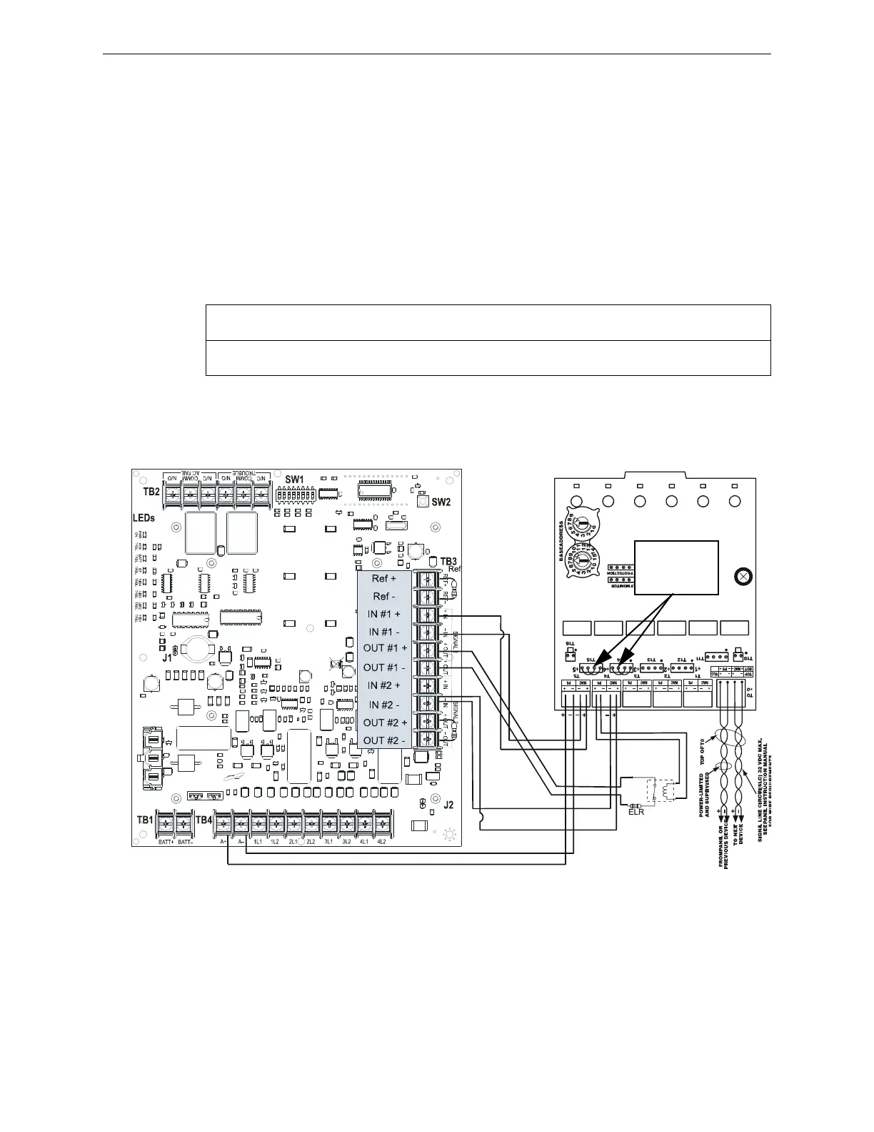
mounted on the Control board shown in Figure 5.4.
Figure 5.4 Wiring for Split Alarm Mode
Notes for Figure 5.4:
1. When the power supply is in normal/standby state, a trouble will result in an open circuit condition on the
control module output circuit (monitored by the End-of-Line Resistors on TB3). The HPFF’s alarm circuit will
always remain closed in the alarm state. Therefore, the Trouble contacts at TB2 need to be used to report
troubles to the FACP during an alarm. Section 4.1, “Supervised Functions and Field Wiring”.
2. Do not loop wires under screw terminals. Break wires to maintain proper supervision.
3. The value of the ELRs (End-of-Line Resistors) across TB3 terminals depends on the control module used.
4. For a list of compatible devices, refer to Appendix A, “Device Compatibility”.
5. The same gauge wire must be used if two conductors are connected to the same terminal of any terminal block.
6. Do not complete a continuous circuit around the screw terminal. There must be two separate wires on either
side of the screw at the terminal block. “T-tapping” is absolutely NOT ALLOWED.
SW8
ON
SW7
N/A
SW6
OFF
SW5
ON
SW4
OFF
SW3
ON
SW2
ON
SW1
OFF
NAC outputs circuits 1 & 2 will have sync for System Sensor device. NAC outputs circuits 3 & 4 will have a
Temporal signal.
hpff8-spl-6up.wmf
Install jumpers
supplied
with module
Alarm Polarity Shown
Supervision
Relay
 Loading...


