HPFF12 NAC Expander — P/N 53576:B 11/24/2010 13
LED Indicators System Overview
1.5 LED Indicators
1.6 Specifications
Refer to Section 1.1, “Control Circuit Board”, on page 15 for terminal locations.
Primary AC Power — TB1 (on 24 VDC power-supply circuit board)
• HPFF12 and HPFF12CM: 120 VAC, 60 Hz, 5.0 A.
• HPFF12E and HPFF12CME: 240 VAC, 50 Hz, 2.80 A.
• Wire size: 14AWG (2.08 mm²) with 600 V insulation.
Initiating Device Signal Inputs — TB3 (on Control circuit board); terminals SIGNAL1: +IN,
–IN, +OUT, –OUT, and SIGNAL2: +IN, –IN, +OUT, –OUT.
• Supervised by FACP or initiating device, power-limited.
• A supervisory relay must be used if initiating device is a power source.
• Available for one of the following:
– 4-wire inputs; or
– 2-wire inputs and an ELR; or
– facilitate multiple unit systems.
• Trigger input voltage: 12 and 24 VDC.
• Input trigger draw in alarm polarity:
– 12 VDC, 5.68 mA maximum per input.
– 24 VDC, 12.26 mA maximum per input.
• 12 AWG (3.31 mm²) to 18 AWG (0.821 mm²).
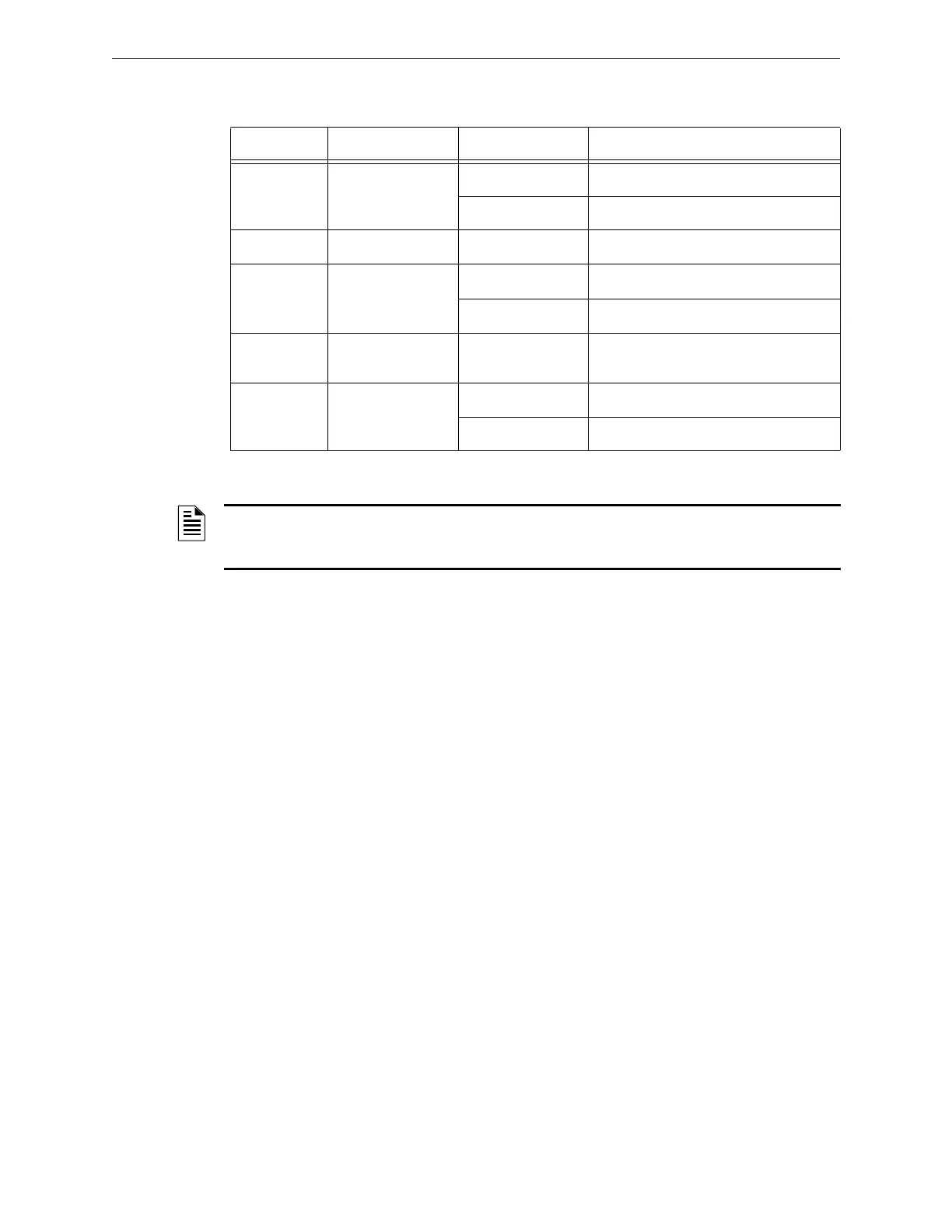
Indicator Name State Trouble Condition
LED 1, 2, 3, 4 SIG(1, 2, 3, 4) TRBL
Blinking NAC Trouble Memory
Steady illumination Open or shorted NAC
LED 5 GF TRBL Steady illumination An earth ground fault is present
LED 6 BAT TRBL
Blinking Charger Fault
Steady illumination Low or missing battery
LED 7 AUX TRBL Steady illumination Excessive loading or shorted auxiliary
output
LED 8 POWER ON
Blinking Low (brown-out) or missing AC input
Steady illumination Normal/Standby
Table 1.1
NOTE: If all four SIG TRBL LEDs are illuminated steady, check if the reference ELR resistor is
missing or doesn’t match the ELR resistors used to terminate the Class B circuits. Otherwise,
each NAC must have a trouble.
 Loading...


