Honeywell Portable Generator Service Manual www.honeywellgenerators.com 9-7
ALTERNATOR
D—EXCITER WINDING CONNECTOR
Resistance Specifications:
• HW4000 Model - 3.3-3.8 Ω
• HW5500 Model - 2.3-2.7 Ω
• HW5500E Model - 2.3-2.7 Ω
• HW6200 Model - 2.1-2.5 Ω
• HW7500E Model - 1.7-1.8 Ω
Using an ohmmeter, measure resistance between the two
blue wires. If specified resistance is not obtained, replace
stator.
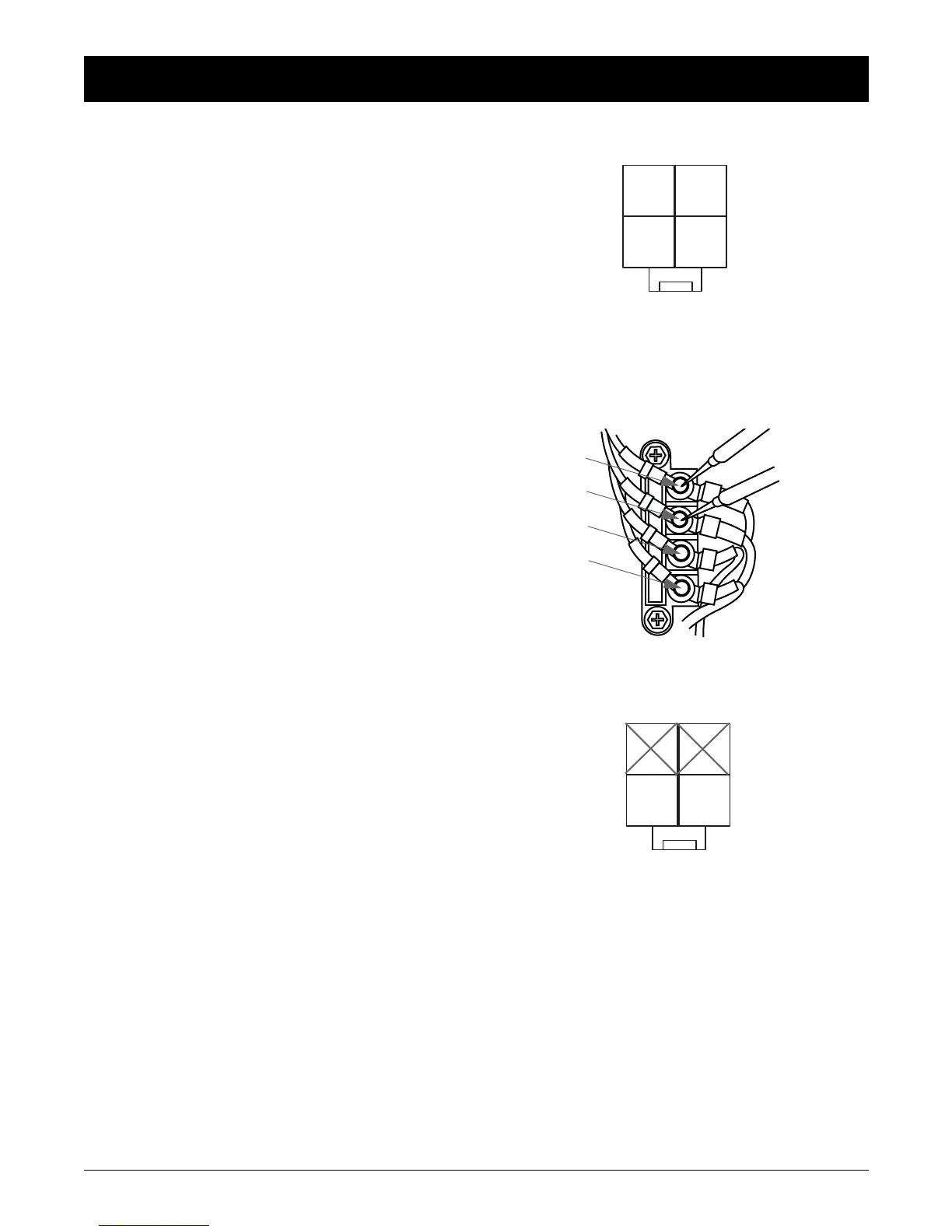
E—MAIN WINDING TERMINAL BLOCK
Resistance Specifications:
• HW4000 Model - 1.5-1.8 Ω
• HW5500 Model - 0.85-1.0 Ω
• HW5500E Model - 0.85-1.0 Ω
• HW6200 Model - 0.6-0.9 Ω
• HW7500E Model - 0.5-0.6 Ω
Using an ohmmeter, measure resistance between the
brown and blue wires. If specified resistance is not
obtained, replace stator.
F—ROTOR WINDING CONNECTOR
Resistance Specifications:
• HW4000 Model - 38-43 Ω
• HW5500 Model - 50-55 Ω
• HW5500E Model - 50-55 Ω
• HW6200 Model - 51-56 Ω
• HW7500E Model - 55-60Ω
Remove brushes and measure resistance between slip
rings.
If specified resistance is obtained at slip rings but not at
brush terminals, clean or replace brushes.
If specified resistance is not obtained at slip rings, clean or
replace rotor.
 Loading...