N
KRA 405B RADAR ALTIMETER INSTALLATION MANUAL
Page 1-3
006-10536-0010 Rev. 10 Oct/2005
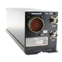
The KRA 405B Radar Altimeter System consists of the KRA 405B Receiver/
Transmitter, the KNI 415 or KNI 416 Indicator, and two (2) KA 54A Antennas.
The entire system is solid state except for a servo mechanism and relay
in the Indicator.
The KRA 405B Radar Altimeter replaces the KRA 405 altimeter. The KRA 405B
is electrically compatible with the same indicators and antennas as the
KRA 405.
NOTE: The connectors for KRA 405 and KRA 405B are not compatible.
1.2 ACRONYMS AND ABBREVIATIONS
ACRONYM MEANING
AGL Above Ground Level
ARINC Aeronautical Radio Incorporated
EUROCAE The European Organization for Civil Aviation Electronics
FAA Federal Aviation Administration
FCC Federal Communications Commission
FTZ Fernmeldetechischeszentralamt (German)
Hz Hertz
IF Intermediate Frequency
kHz kilohertz
GHz Gigahertz
MHz Megahertz
PEO Precision Equipment Output
P/N Part Number
RTCA Requirements and Technical Concepts for Aviation
R/T Receiver/Transmitter
TSO Technical Standing Order
VSWR Voltage Standing Wave Ratio
XX Part numbers ending in XX denotes the highest revision available (Example: 006-
10536-00XX)

 Loading...