20 Installation Instructions MB-Secure 1000/2000/3000/4000/5000/6000
If Intruder alarm systems also display fault signals optically or acoustically in armed mode (allowed only for
displays outside the protection zone), the power consumption of these displays must also be taken into account.
In addition, VDE guidelines and local public utility regulations must be complied with.
3.3 Installation in 19"- Cabinet/housing (third-party products)
If possible, assembly plates item no. 013106 should be used, since modules can be fixed without difficulty in
using them.
In addition, these assembly plates have appropriate clamps for a proper installation of the cable shields. For
more on this, see the chapter Grounding/shielding.
The following points must be kept in mind in the selection and installation of the 19" housing:
* Option of installing the back panel assembly plates item no. 013106
* Option of installing monitoring contact for the door (cover contacts)
* Electrically conductive connection of all metallic housing parts to one another
* Option to lead-seal the locking mechanism(s)
In addition, for VdS systems, the relevant VdS guidelines must be complied with!
3.4 Installing power supply unit and battery in housing ZG20.
One of the three mounting screws for the housing ZG20 is behind the power supply / charger and therefore the
housing must first be mounted on the wall.
Then the power supply / charger 013970 is to be attached in the lower left section of the housing using the three
screws provided for this purpose.
In order to attach the battery, the mounting bracket provided for this must first be removed. Then two adhesive
strips are to be attached to the bottom of the battery. With these, the battery can now be placed centered under
the mounting bracket on the floor of the housing. A distance of at least 5 mm should be maintained from the
right edge of the housing. After applying manual pressure to fix the adhesion, the mounting bracket can be
placed in its final position for attachment.
Then the power supply / charger can be connected according to the installation wiring instructions.
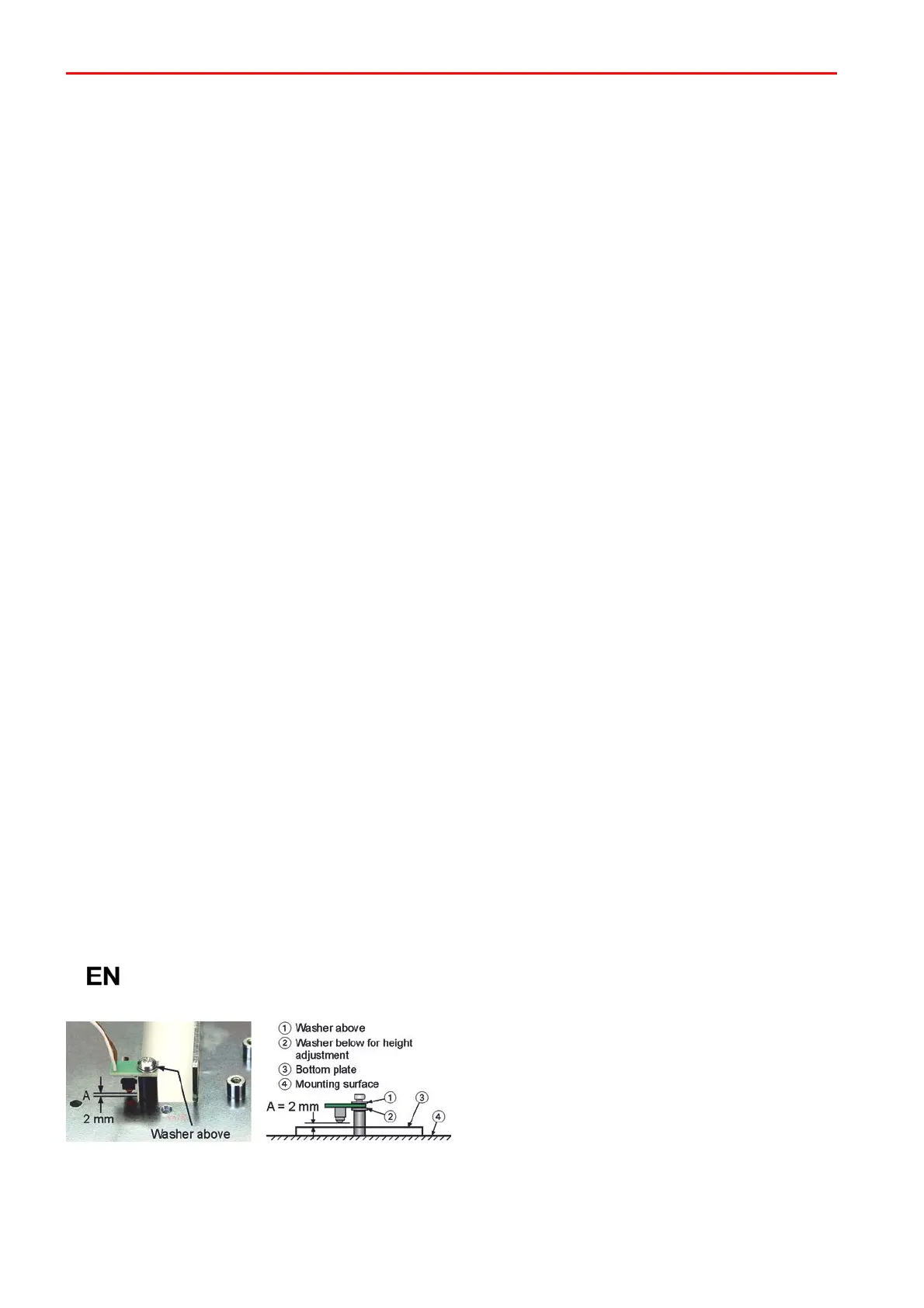
3.5 Installing the tear-off monitoring contact
According to European standards, tear-off monitoring contacts have to be installed in Class 3
devices.
Spacers and the board with the breakaway protection
switch are screwed to the mounting surface as
shown. The distance "A" between the switch and the
back of the housing is approx. 2 mm and must be
adjusted with washers if necessary.
 Loading...


