Installation Instructions MB-Secure 1000/2000/3000/4000/5000/6000 29
3.10.3 Sample cable calculation for users
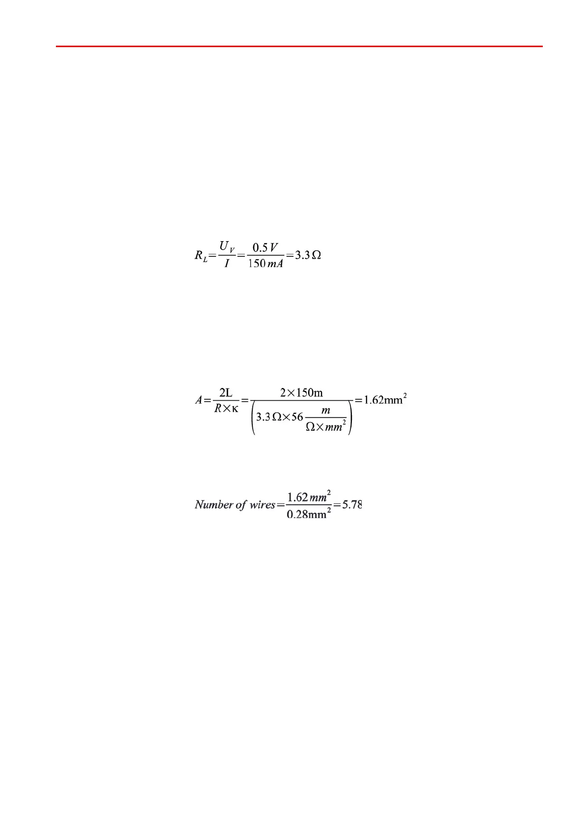
Assumption: The cable length to be installed is approximately 150 meters. Users connected to a BUS
connection require a maximum current of 150 mA. The installation should be performed using
telephone cable (cable diameter 0.6 mm = 0.28 mm
2
). The max. loss of potential is 0.5 V DC. A
telephone cable is a copper cable with a conductivity of k (Kappa) 56 m/Ωmm
2
.
Calculation of line resistance
R
L
= Line resistance
U
V
= max. permissible voltage drop
I = Current consumption of all BUS users on a BUS connection (branch).
Calculation of cross-section required
A = wire cross section per connection
R
L
= line resistance (+12 V DC and 0 V total)
k = specific conductance value of copper
L = cable lengths
Determination of number of wires
This means that 6 wires are required in parallel for each connection (+12V DC and 0V).
 Loading...


