Installation Instructions MB-Secure 1000/2000/3000/4000/5000/6000 33
4 Start-up procedure
4.1 Preparations before start-up
The operation of the control panel requires operating and display elements that provide information about the
current status of the system and allow the operator or installer to gain access to system functions.
In contrast to normal mode, the control panel may be programmed only via a PC/laptop using the "IQ
PanelControl” software (via Ethernet). After programming, no connection to the network is allowed.
4.2 Programming of BUS users
4.2.1 BUS-2 users
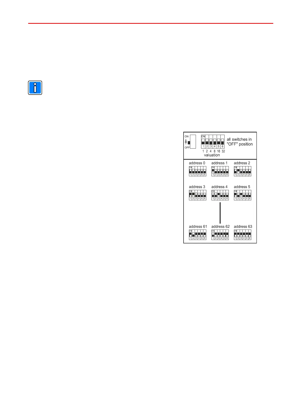
The individual users have a 6 way programming switch to configure
user addresses between 0 and 63.
Connections on the computer/connection PCB are mutually isolated
BUS-2 connections with separate fuses. The maximum number of
BUS-2 users on each connection is 64.
4.3 Initial start-up procedure
All system components must have been properly installed. Measure all lines from the connection to the control
panel in order to detect any line interruptions or short circuits. Ensure that there is no earth fault. Cover contacts
of system components and the control panel must be closed. (Simulate cover contacts of the control panel,
possibly using a shorting bar, or keep closed using a magnet). If programmed with tamper monitoring, flash
lamps and sirens must be correctly installed.
BUS user addressing must have been correctly performed.
To place the unit into electrical operation, proceed as follows:
* Disconnect the computer/connection PCB from the power supply/charger unit.
* Switch on the power supply.
* Measure the battery charging voltage at the battery connection cable (+13.8V DC).
* If need be, set the battery charging voltage (see description, power supply/charger unit).
* Connect the battery(ies).
* Reconnect the power supply/charger unit to the connection PCB.
* The control panel goes through its boot procedure. The four “Status information" LEDs light statically
for around 30 seconds.
The green LED (2nd from the left) indicates successful termination of the boot and initialization process:
Blinking -> Not programmed
Steady on -> Operation/initialization successful
Diagram BUS-2 programming switch
 Loading...


