Installation Instructions MB-Secure 1000/2000/3000/4000/5000/6000 45
7.9 Connection to power supply / charger unit 013950/013960
according to VdS guidelines
for 1
The operating voltage of the individual bus branches has to be supplied via the "external load"
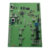
connections on the power supply unit. In addition, the fuse for the corresponding bus branch is to be
removed on the computer/connection PCB.
for 2
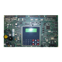
The "external load" connection on the computer/connection PCB may not exit the housing. It can be
used to connect a transmission device inside the housing for example.
for 3
A separately routed BUS branch has to be used for each protection area for BUS 2 users.

 Loading...
