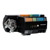
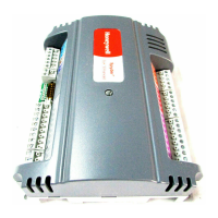
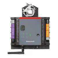
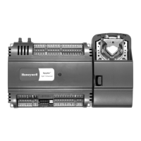
I/O TERMINALS
CAUTION
Failure to observe the following max. permissible
current outputs of the power output terminals will
result in damage to the device.
Max. Current Output of Power Output
Terminals of 24 VAC Controllers
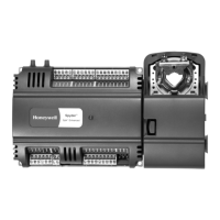
The 24 VAC power output terminals of the WEB-RL6N
controllers are terminals 5, 6, 35, 39, 43, and 44 plus pin 4
of the controller's RJ45 interface.
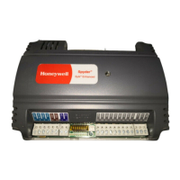
The 24 VAC power output terminals of the WEB-RS5N
controllers are terminals 3, 4, 22, 23, 24, 25, 27, and 31
plus pin 4 of the controller's RJ45 interface.
The maximum permissible combined current output of
these 24 VAC power output terminals is 300 mA.
Relay Outputs
CAUTION
Mixing of different voltages within the relay block is
not allowed.
The terminal blocks containing the controller's relay
outputs are orange. Relay output types: See Table 3 pg.4.
NOTE: If inductive components are to be connected to
the relays and if these relays switch more often
than once every two minutes, these components
must be prevented from causing harmful
interference to radio or television reception
(conformance with EN 45014).
Relay Current Limitations
If the triacs are supplied with current from an external
source, then a maximum of two relays may be loaded with a
max. of 4 A per relay, even if two triacs are each
simultaneously loaded with max. 300 mA.
If the triacs are supplied with current from an internal
source, a maximum of two relays may be loaded as follows:
a max. load of 4 A for a relay serving a fan and a max. load
of 10 A for a relay serving a reheat, even if one triac is
simultaneously loaded with 300 mA.
Triac Outputs
NOTE: Recommended fuse (F1): 1.25 A time-lag fuse
(IEC). User must consider the correct voltage and
max. breaking capacity / interrupting rate (line
voltage urgently requires high breaking capacity /
interrupting rate).
The terminal blocks containing the controller's triac
outputs are orange.
These triac outputs can be used for a variety of different
functions, e.g., for connection to either a floating drive or to
a thermal actuator. Once the triac outputs have been
programmed, the corresponding devices can then be
connected to them directly.
NOTE: The VC6983 actuator is intended for use at relay
outputs, only and must not be used at the con-
troller's triac outputs.
Triac Current Limitations
The maximum allowed current with which the ensemble of
a controller's triacs may be loaded is dependent upon
whether the given model is powered with 24 VAC, upon
whether the outputs are supplied by the controller's
internal transformer or by an external current supply).
Specifically:
▪ In the case of 24 VAC models, the ensemble of a con-
troller's triacs may be loaded with 600 mA.
However, regardless of model and regardless of whether
the triacs are supplied internally or externally, a single triac
must never be loaded with a current of more than 300 mA
(320 mA for maximum 2 minutes).
Nevertheless, the ensemble of triacs can be loaded for very
short periods of time (on the order of milliseconds) with a
current on the order of 2500 mA typically encountered
when switching on multiple thermal actuators.
Universal Inputs
The terminal blocks containing the controller's universal
inputs are blue. Universal input types: See Table 4.
The universal inputs are protected against voltages of max.
29 VAC and 30 VDC (due to, e.g., miswiring).
 Loading...
