SPYDER MODEL 5 ROOM CONTROLLERS − INSTALLATION GUIDE
3 31-00281ES-01 (EN1B-0664GE51 R0819)
When mounted vertically on a DIN rail, the unit must be
secured in place with a stopper to prevent sliding.
Wall Mounting/Dismounting
The unit can be mounted on floors, walls, and ceilings in
any desired orientation. (See also section "Ambient
Environmental Limits" on pg. 17 for temperature range
restrictions with floor/ceiling mounting.)
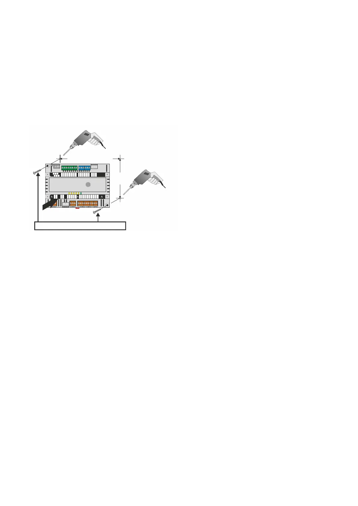
The unit is mounted by inserting optional screws
(recommended: DIN EN ISO 7049 – ST4,2x22 – C - H)
through the corresponding screwing noses.
Fig. 7. Drilling template (view from above)
After mounting the unit onto the wall, snap the appropriate
terminal protection covers (see Fig. 4 and Fig. 5 on pg. 2)
into place onto the housing by hand.
NOTE: In the case of wall-mounting, two optional terminal
protection covers (in the case of the WEB-RL6N
[large housings]: IRM-RLC; in the case of the WEB-
RS5N [small housings]: IRM-RSC) must be
installed in order to comply with IP30.
The covers can be fixed into place using optional screws
(recommended: DIN EN ISO 7049 – ST2,9x9,5 – C (F) – H).
To remove a cover, place a screwdriver in the two leverage
slots (marked with arrows) and pry it loose.
TERMINAL ASSIGNMENT
General
For a complete list of all terminals and a description of their
functions, see Table 2 and Table 6 on pg. 4 and pg. 6.
NOTE: All terminal blocks capable of carrying either low
voltage or line voltage are orange-colored.
Depending upon the given hardware model, the delivery
includes a plastic bag containing additional, removable
terminal blocks.
Every controller features a terminal assignment label on
the top of the housing.
Power Supply Terminals
▪ In the case of the 24VAC models, power is supplied via a
removable terminal plug (terminals 3 and 4).
See also section "Power Supply" on pg. 9.
Input / Output Terminals
The controller features rows of terminal blocks on the top
and bottom.
▪ In the case of the WEB-RL6N (large housing), the
controller has double rows of analog outputs (AOs) and
universal inputs (UIs) at the top and a single row of
binary outputs (BOs) - triacs (TRs) and relay outputs
(ROs) - at the bottom.
▪ In the case of the WEB-RS5N (small housing), the
controller has a single row of analog outputs (AOs) and
universal inputs (UIs) at the top and a single row of
binary outputs (BOs) - triacs (TRs) and relay outputs
(ROs) - at the bottom.
NOTE: According to VDE guidelines, it is not allowed to
mix low-voltage and high-voltage signals on the
relays and triacs.
See also section "I/O Terminals" on pg. 12.
Communication Interfaces
All models of the controller feature the following communi-
cation interfaces:
▪ A Sylk Bus interface (WEB-RS5N: terminals 20 and 21;
WEB-RL6N: terminals 30 and 31), for connection to
TR40x/42x Wall Modules;
▪ A BACnet MS/TP interface (WEB-RS5N: terminals 40,
41, and 42; WEB-RL6N: terminals 62, 63, and 64);
▪ An RJ45 connector for future use with BACnet WiFi
Adapter;
▪ A second RS485 interface for future use with Modbus.

 Loading...