SPYDER MODEL 5 ROOM CONTROLLERS − INSTALLATION GUIDE
31-00281ES-01 (EN1B-0664GE51 R0819) 6
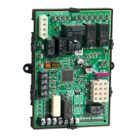
Table 6. WEB-RL6N Room Controllers: Overview of terminals and functions (by model)
Removable 24 VAC power supply input
Aux. output voltage (24 VAC) for all triacs
Aux. terminal for triac neutral wiring (internally connected with terminals 10 and 13)
Triac input voltage (24 VAC) for all triacs; triac-switched
Aux. terminal for triac neutral wiring (internally connected with terminals 7 and 13)
Aux. terminal for triac neutral wiring (internally connected with terminals 7 and 10)
Output of Relay 4, Input for Relay 4
Aux. terminal for relay neutral wiring
Aux. terminal for relay neutral wiring
Input for Relay 1, Output of Relay 1
Input for Relay 2, Output of Relay 2
Input for Relay 3, Output of Relay 3
RS485 Modbus interface, corr. GND, + aux. power (24 VAC 20%, 50/60 Hz)
Removable interface for Sylk Bus
24 VAC power for field devices
24 VAC power for field devices
24 VAC power for field devices
24 VAC power for field devices
Removable BACnet MS/TP interface and corresponding GND
Relay output types Table 3: See. Universal input types: Table 4. Analog output types: See Table 5.
--: Terminal not used.
X: Terminal used.
Type x: Type of an I/O as per its characteristic. Mode details given on each type in following tables.

 Loading...