T775 SERIES 2000 ELECTRONIC STAND-ALONE CONTROLLERS
63-7147—3 8
T775 APPLICATIONS
Water Source Heat Pump Loop Water
Controller – T775B
Application Description
Water is circulated in a loop to remove waste heat and to
provide cooling from a multiple heat pump system. In this
example, the T775B controls heating and cooling systems to
maintain the loop water temperature between preset upper
and lower limits. Alarms are sounded to annunciate
abnormally high or low water temperatures.
NOTE: T775R reset models can also be used in this
application.
Sensor Designation
This device application only requires one sensor. Sensor A is
mounted in a well, located in the main loop water line before
the water source heat pump take-offs.
Operation
In this example, if the loop water temperature drops to 55° F
(13° C), heat is added to the system by the boiler (Relay 1)
until it reaches the setpoint. If the temperature drops further,
Relay 2 sounds the low temperature alarm at 54° F (12° C).
If the loop water temperature rises to 95° F (35° C), Relay 3
brings on cooling. If the temperature rises to 96° F (36° C),
Relay 4 powers the high temperature alarm.
NOTE: If no alarms are present, Relay 2 and 4 may be used
as additional heating and cooling relays.
Programming Example
Relay 1: Enables boiler circuit
Program for:
—Heat
— Setpoint = 65° F (18° C)
— Differential = 10° F (-12° C)
Relay 2: Low temperature alarm circuit
Program for:
—Heat
— Setpoint = 55° F (13° C)
— Differential = 1° F (-17° C)
Relay 3: Enables cooling circuit (heat extraction)
Program for:
—Cool
— Setpoint = 85° F (29° C)
— Differential = 10° F (-12° C)
Relay 4: High temperature alarm circuit
Program for:
—Cool
— Setpoint = 95° F (35° C)
— Differential = 1° F (-17° C)
Setpoints may differ according to equipment manufacturers.
See their recommendations.
IMPORTANT
After the desired value is selected, be sure to press
the # or $ or HOME button in order to save that
value in the controller’s memory.
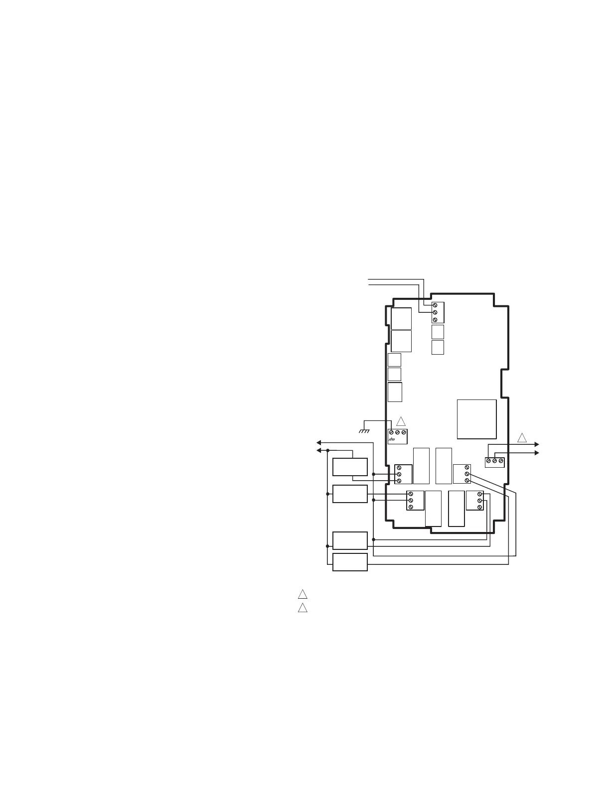
Wiring
All output relays should have a common power wiring source,
which may or may not be the same as the T775 power wiring.
Fig. 3. T775B Wiring - Loop Water Controller.
L1
(HOT)
L2
SENSOR A
(LOOP WATER)
C
NO
NC
C
NO
NC
C
NC
NO
C
NC
NO
T
T
HI TEMP
ALARM
RELAY
1
SUBTRACT
HEAT
LO TEMP
ALARM
C
+
ADD
HEAT
RELAY
4
RELAY
3
RELAY
2
T775B
120
COM
240
1
2
120 VAC
M24863
POWER WITH 24 VAC OR 120/240 VAC AT THE APPROPRIATE TERMINAL BLOCK.
24 VAC POWER TERMINAL BLOCK.
1
2

 Loading...