12
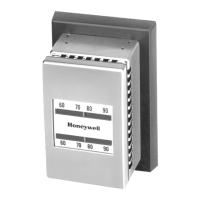
TP970 AND TP9600 SERIES PNEUMATIC THERMOSTATS
77-9382—177-9382—1 R. F. 10-97
Home and Building Control
Honeywell Limited-Honeywell Limitée
155 Gordon Baker Road
North York, Ontario
M2H 3N7
Home and Building Control
Honeywell Inc.
Honeywell Plaza
P.O. Box 524
Minneapolis MN 55408-0524
Printed in U.S.A. on recycled
paper containing at least 10%
post-consumer paper fibers.
Operation
Main air enters through the main air passage. Filtered air
goes to Logic Module A and into the pilot chamber of the
valve unit flow amplifier (see arrows in Fig. 17). When the air
reaches Logic Module A, it cannot pass because the spring-
loaded diaphragm is adjusted to pass only 18 psi (124 kPa)
of air. In this condition, no air pressure is applied to the
diaphragm of Logic Module B and it stays in the up position,
allowing air to pass from the pilot chamber through Port B1.
This air is routed on to the flapper-nozzle of the cooling
bimetal and the Thermostat operates in a cooling mode. The
spring-loaded diaphragm of Logic Module B stays open until
air pressure is applied from Logic Module A.
When main air enters the Thermostat at 18 psi (124 kPa), as
previously described for the cooling cycle, the spring of
Logic Module A is overcome and air passes through the
Module. The air pressure is applied to the diaphragm of
Logic Module B, closing off Port B1, and opening Port B2.
Now the air is directed to the flapper-nozzle of the heating
bimetal and the Thermostat controls in the heating mode.
TP974A ROOM TEMPERATURE
SENSOR
General
The TP974A (Fig. 19, 20) is a bimetal-element, proportioning
temperature sensor for either two- or one-pipe applications.
The sensor bimetal is direct acting (signal pressure
increases as the temperature increases). The TP974A is
factory calibrated for 50 to 100°F (10 to 38°C), for a fixed
span of 50°F (28°C). This span is equal to a corresponding
pressure change of 12 psi (83 kPa) for 3 to 15 psi (21 to
103 kPa). The TP974A has no setpoint adjustment and the
TR is factory preset.
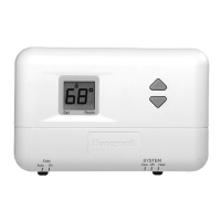
Fig. 19. Cross Section of TP974A—Two-Pipe Application.
Fig. 20. Cross Section of TP974A—One-Pipe Application.
Operation
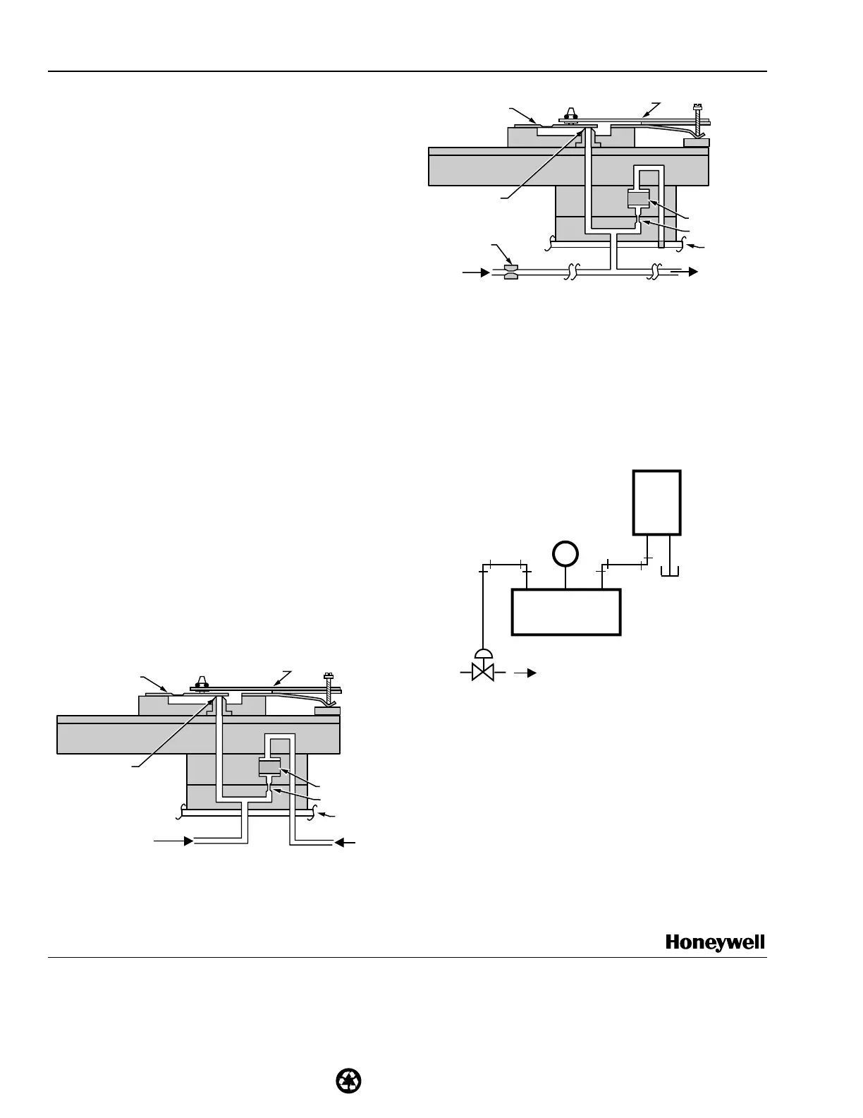
Figure 21 shows a TP974A used with a direct-acting
RP920A Controller for control of a normally open heating
valve. A fall in temperature at the TP974A lowers the signal
to the RP920A. The RP920A responds by decreasing the
BLP to the valve to admit more hot water to the heating coil.
SUPPLY N.O.
RP920A
(DA)
21
3
M
TP974A
C6066
Fig. 21. Typical TP974A Operation.
BIMETAL
RESTRICTOR
MAIN
LINE
BRANCH SIGNAL
PRESSURE
(TO INDICATION
GAGE OR CONTROL)
NOZZLE
FLAPPER
C6064
FILTER
BACKPLATE
BIMETAL
RESTRICTOR
MAIN
LINE
EXTERNAL
RESTRICTOR
NOZZLE
FLAPPER
C6065
FILTER
BACKPLATE
TO
CONTROLLED
DEVICE
 Loading...