8
TP970 AND TP9600 SERIES PNEUMATIC THERMOSTATS
77-9382—1
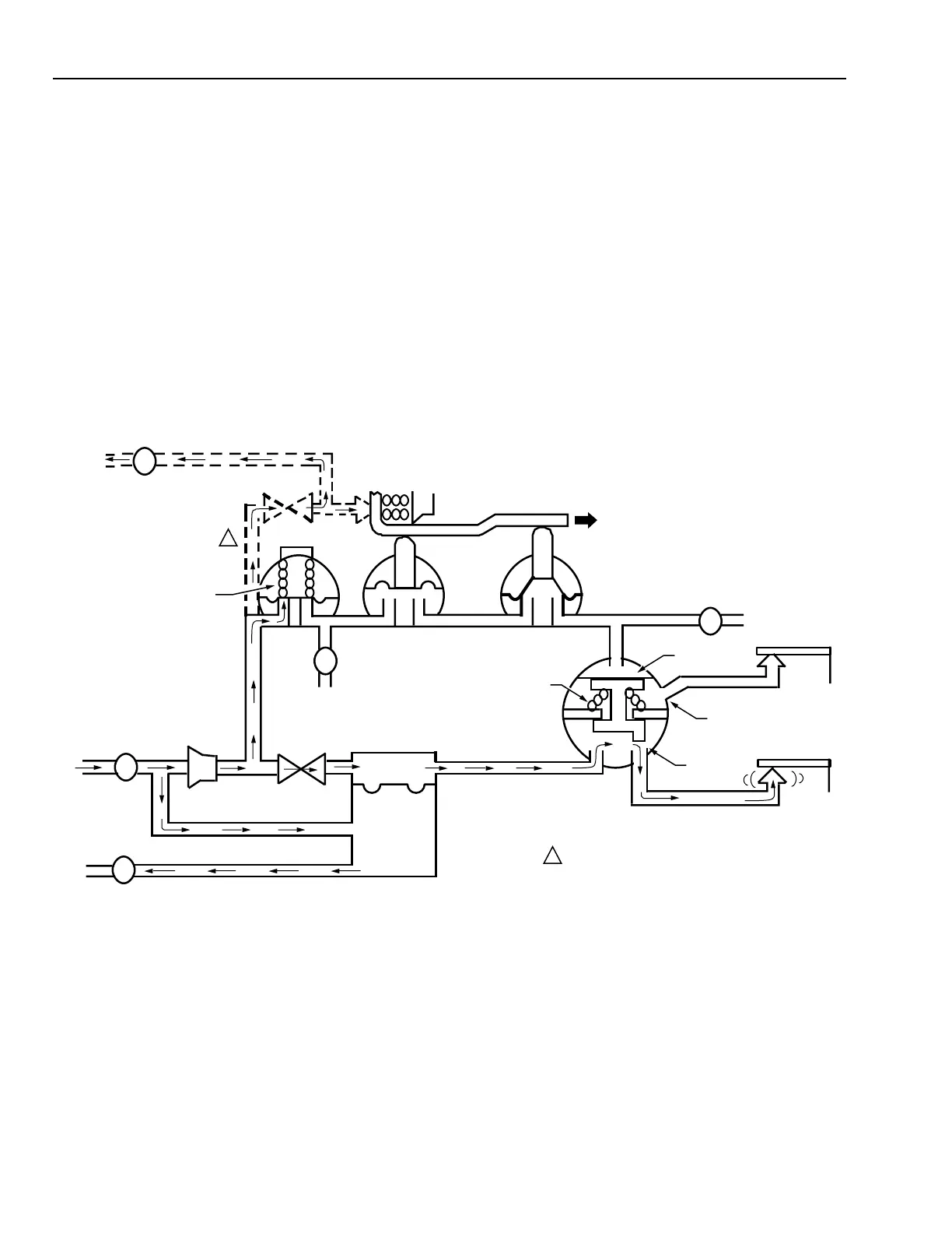
Daytime Operation
Figure 13 shows airflow through the Thermostat during
daytime operation. The main air pressure is at the lower,
daytime operating pressure of 13 psi (90 kPa).
Air enters the Thermostat through the main line, passes
through a screen, then diverts into the valve unit and through
the multistage filter. The arrows in Figure 13 show main air
traveling to Logic Module A, which is closed because the
adjustable spring is set to open only at the higher nighttime
pressure. Main air passes through the integral restrictor, into
the pilot chamber of the valve unit, and in to Logic Module B.
The spring holds Port B1 open because there is no air
pressure against the top of the diaphragm of Logic Module
B. This action allows air to pass through Port B1 to the 13 psi
(90 kPa) (DAY) nozzle-flapper. The Thermostat now operates
on a daytime cycle at the daytime setpoint. The valve unit
operation is identical to that described in the Valve Unit
Operation section.
Fig. 13. TP971 and TP9610 Operation on Day Cycle—Main Air Pressure 13 psi (90 kPa).
Nighttime Operation
In Figure 14, the main air pressure is at 18 psi (124 kPa) for
nighttime operation. The airflow, shown by arrows, is the
same as the daytime cycle up to Logic Module A and Logic
Module B. The main air pressure, 18 psi (124 kPa), is now
enough to overcome the spring-loaded diaphragm in Logic
Module A. Because the manual override lever is in the AUTO
position, the air passes through Logic Module A, and then
through Logic Modules C and D. This air pressure forces the
diaphragm of Logic Module B downward, closing Port B1
and allowing air to pass through Port B2. The airflow then
passes to the 18 psi (124 kPa) (NIGHT) nozzle-flapper. In
this condition, the Thermostat operates on a nighttime cycle.
Valve unit flow amplifier operation is identical to that
described in the Valve Unit Operation section.
B BLEED 1
F
FILTER
RESTRICTOR
R
VALVE
UNIT
SECONDARY
BRANCH
S
S
S
B
DAY/AUTO LEVER
MANUAL DAY
LOGIC
MODULE C
LOGIC
MODULE D
SPRING
LOGIC MODULE A
DOTTED LINES INDICATE THE SECONDARY
BRANCH LINE INTEGRAL TO THE TP971C
BRANCH LINE
MAIN LINE
PILOT
CHAMBER
SPRING
BLEED 2
DIAPHRAGM
PORT B2
PORT B1
13 PSI (90 kPa)
DAY
18 PSI (124 kPa)
NIGHT
LOGIC
MODULE B
C6058-1
1
1
 Loading...