60-2080—8 4
ACCESSORIES:
Transformer AT72D: (40 VA) for all V88 models.
126590 Adjustable Bleed Valve Assembly: Consists of
adjustable bleed valve with sleeve and compression
nut for connecting to 1/4 in. tubing; see Fig. 8.
(Not available for valves with BSP.PI. threads.)
Bleed Orifice: Fixed (see Table 2 for appropriate size):
124674 Orifice: 0.011 in. [0.28 mm] diameter.
122160 Orifice: 0.018 in. [0.46 mm] diameter.
126070 Orifice Tool: Required for field mounting a
bleed orifice (in valves with NPT threads only).
GAS VALVE SIZING
1. Check the burner nameplate for (a) the type of gas
used, and (b) the gas flow capacity. The capacity will be
listed in Btu/h (Btu per hour) or in cf/h (cubic feet per
hour).
2. Call the gas utility for information on (a) the specific
gravity (sp gr) and (b) Btu per cubic feet (Btu/cu ft) for type
of gas used.
3. Find the capacity in cf/h. If the capacity is listed in
Btu/h, convert to cf/h by the following formula.
Capacity in cf/h = Btu/h (from burner nameplate)
Btu/cu ft (from gas utility)
4. For gases with specific gravities other than 0.64,
multiply the burner cf/h by the conversion factor in Table 3.
5. Use the corrected capacity in cf/h when determining
the gas valve size in Fig. 2.
6. Determine the maximum pressure drop across the
valve, and draw a horizontal line at this pressure in Fig. 2.
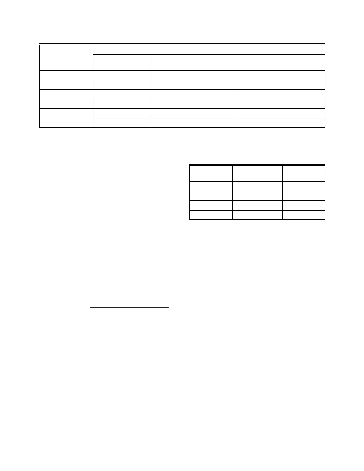
TABLE 3—CONVERSION FACTORS.
a
Time to reach 80% gas flow at fully open position. Inlet pressure; 4.2 in. wc [1.05 kPa] for 1 to 2 in. valves; 5 in. wc [1.25 kPa]
for 2-1/2 and 3 in. valves. Pressure drop across valves at fully open position. 0.2 in. wc [0.05 kPa] for 1 to 2 in. valves; 1 in. wc
[0.25 kPa] for 2-1/2 and 3 in. valves.
TABLE 2—EXTENDING VALVE OPENING TIME
a
BY ADDING A BLEED ORIFICE.
V48A,F,J; V88A,J
SPECIFICATIONS
7. Draw a vertical line in Fig. 2 at the capacity (cf/h)
previously determined. Use the corrected capacity for a
gas with a specific gravity other than 0.64.
8. Use the valve size at the intersection of the horizontal
and vertical lines. If the intersection is between valve sizes,
use the next higher valve size to the right.
TO SIZE TWO IDENTICAL VALVES PIPED
IN SERIES
1. Find the cf/h for the type of gas used.
2. Consider both valves as one unit. Determine the total
maximum pressure drop across the unit.
3. Find the pressure drop across the first valve by as-
suming it to be 45 percent of the total pressure drop.
4. Find the valve size from Fig. 2.
5. The second valve will be the same size as the first
valve.
Valve Opening Time (sec)
Valve Size (in.) No. Orifice
Orifice no. 122160,
0.018 in. [0.46 mm]
Orifice no. 124674,
0.011 in. [0.28 mm]
11 2 3
1-1/4 1 5 6
1-1/2 1 5 6
2 4 15 32
2-1/2 4 23 37
3 5 24 37
Type of
Gas
Average Specific
Gravity
Multiply
cf/h by
Manufactured 0.60 1.033
Mixed 0.70 0.956
LP—Propane 1.53 0.647
LP—Butane 1.98 0.569
 Loading...