5 60-2080—8
V48A,F,J; V88A,J
SPECIFICATIONS • INSTALLATION
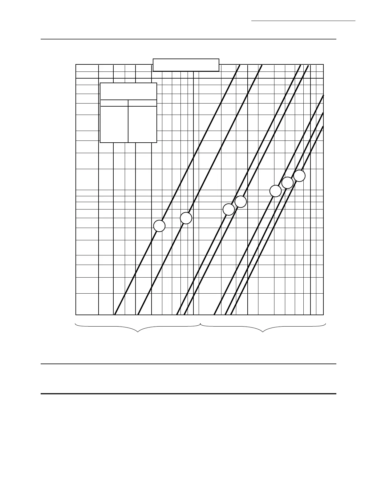
Fig. 2—Pressure drop vs. capacity chart for sizing gas valves.
Installation
WHEN INSTALLING THIS PRODUCT…
1. Read these instructions carefully. Failure to follow
them could damage the product or cause a hazardous
condition.
2. Check the ratings given in the instructions and on
the product to make sure the product is suitable for your
application.
3. Installer must be a trained, experienced, flame safe-
guard control technician.
4. After installation is complete, check out product
operation as provided in these instructions.
PRESSURE DROP VS. CAPACITY
FOR 0.64 SP GR. GAS
A.G.A.RATING FOR
0.64 SP. GR. GAS AT
1 IN. PRESSURE DROP
VALVE SIZE CAPACITY
3/4 IN.
1 IN.
1-1/4 IN.
1-1/2 IN.
2 IN.
2-1/2 IN.
3 IN.
668 cf/h
1021 cf/h
2100 cf/h
2400 cf/h
4178 cf/h
5100 cf/h
5562 cf/h
3/4
1
1-1/4
1-1/2
2
2-1/2
3
1 1.5 2 2.5 3 4 5 6 7 8 9 10 1.5 2 2.5 3 4 5 6 7 8 9 10
MULTIPLY BY 100 MULTIPLY BY 1000
[0.025] 0.1
0.15
[0.05] 0.2
0.25
[0.075] 0.3
[0.1] 0.4
0.5
[0.15] 0.6
0.7
[0.2] 0.8
0.9
[0.25] 1.0
1.5
[0.5] 2
2.5
[0.75] 3
[1.0] 4
5
[1.5] 6
7
[2.0] 8
9
[2.5] 10
M8491
PRESSURE DROP—INCHES W.C. [kPa]
CAPACITY IN CUBIC FEET PER HOUR (cf/h)
FOR GAS WITH SPECIFIC GRAVITY OF 0.64
[1 cf/h = 0.0283 m
3
/hr]
 Loading...