60-2080—8 8
V48A,F,J; V88A,J
INSTALLATION • OPERATION
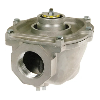
INSTALLATION OF AN OPTIONAL ADJUSTABLE
BLEED VALVE (FIG. 8)
NOTE: This device is not available for valves with BSP.PI
threads.
Screw the 126590 Adjustable Bleed Valve into the
tapping marked BLEED. Be sure to screw the end with the
1/8-NPT threads into the BLEED tapping. Complete the
bleed line connection. Then alternately energize and de-
energize the valve actuator, and adjust the screw on the
bleed valve for the desired valve opening time.
Fig. 8—Installing optional 126590 adjustable
bleed valve.
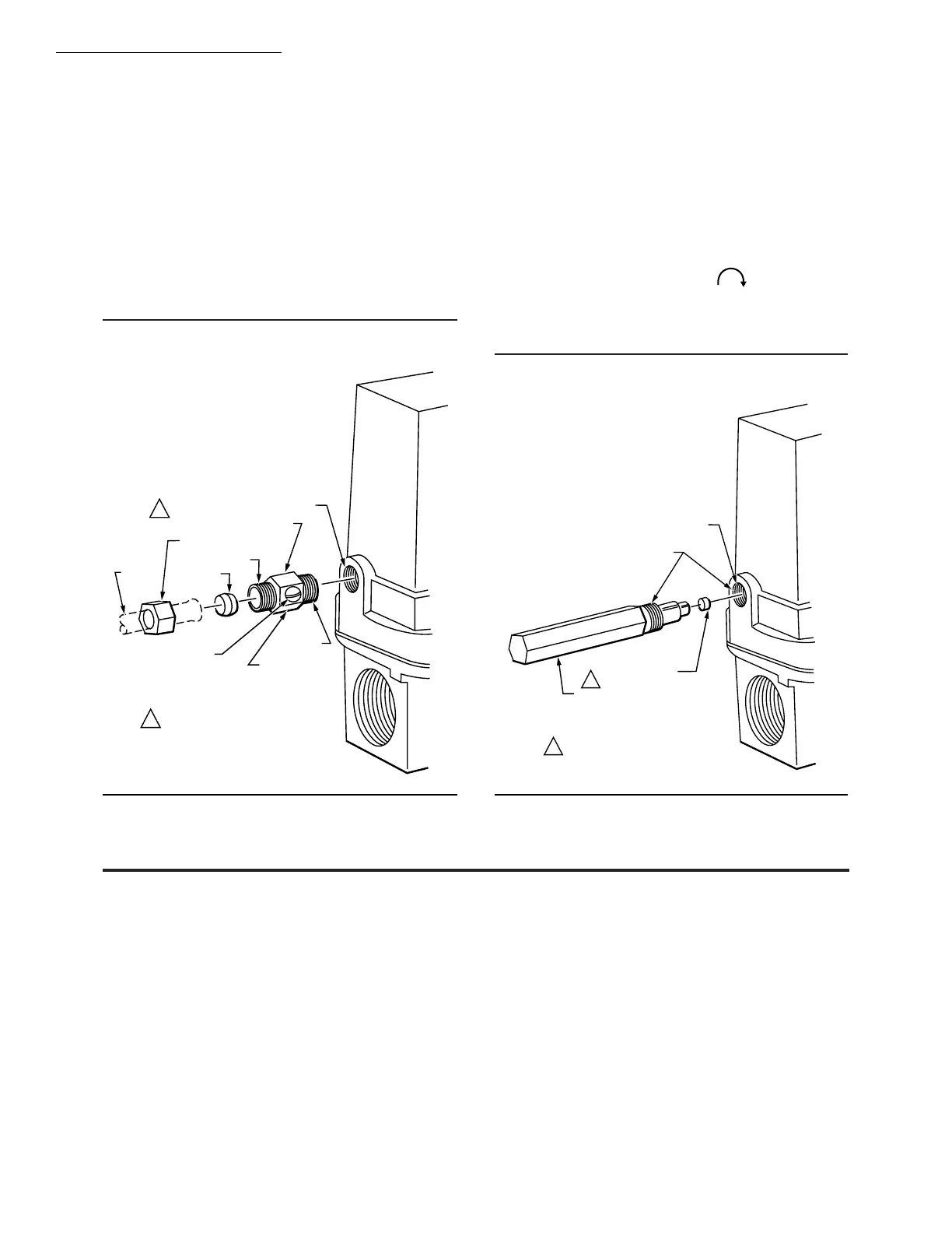
INSTALLATION OF AN OPTIONAL BLEED
ORIFICE (FIG. 9)
NOTE: The orifice tool cannot be used on valves with
BSP.PI threads.
Press the selected bleed orifice (see Table 2) over the
slotted end of the 126070 Orifice Tool. With the tool, insert
the orifice into the bleed port until the tool, threads mate
with the threads in the bleed port. Finger-thread the tool
into the bleed port (turn clockwise ) as far as pos-
sible; then use pliers to seat the orifice. Seating occurs
when the threading stops. Withdraw the tool and complete
the connection of the bleed tubing.
Fig. 9—Installing optional bleed orifice.
Operation
OPERATION OF THE V48 AND V88 (FIG. 10)
When the controller is not calling for heat, the coil is de-
energized. The plunger in the 3-way actuator is in the
DOWN position so the bleed port is closed and the supply
port is open. Gas flows into the top part of the valve. The
gas pressure on top of the diaphragm, the weight, and the
spring hold the valve closed.
On a call for heat, the controller contacts close and the
coil is energized. This pulls the plunger to the UP position,
opening the bleed port and closing the supply port. The gas
in the top of the valve flows out through the bleed port. This
reduces the pressure on top of the diaphragm, allowing the
gas pressure below to lift the diaphragm and open the
valve.
When all the gas has bled off the top of the diaphragm,
the valve is fully open, permitting gas flow to the main
burner.
After the controller is satisfied, the procedure is reversed.
The controller contacts open so the coil is de-energized. The
plunger is released, moving to the DOWN position. This
closes the bleed port and opens the supply port so gas flows
again into the top port of the valve. As the gas pressure on
top of the diaphragm increases, the diaphragm begins to
close. When the pressures on both sides of the diaphragm
are balanced, the valve will be closed. The weight and
spring help to close the valve. If the gas supply fails and
there is no pressure below the diaphragm, the weight and
spring will close the valve.
BLEED TAPPING
126590 ADJUSTABLE BLEED VALVE
SLEEVE
COMPRESSION NUT
1/4 INCH
TUBING
7/16-24 UNS
ADJUSTING SCREW
7/16 INCH HEX
1/8-27 NPT
THIS DEVICE WILL NOT FIT VALVES
WITH BSP.PL THREADS.
1
1
M7290
BLEED PORT
1/8-27 NPT
THIS TOOL WILL NOT FIT VALVES
WITH BSP.PL THREADS.
1
1
M7298
ORIFICE TOOL
BLEED ORIFICE
(SELECTED)
 Loading...