EN2R--9018 9704R1--NE
4
SPECIFICATIONS
The specifications described in this chapter are related to the
main gas valve, by--pass valve and pilot valve (see also
Performance characteristics on page 6.).
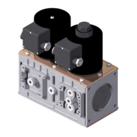
Models
VQ420/25 (DN20 and DN25)
VQ440/50 (DN40 and DN50)
NOTE: DN32 connection is obtained with a flange kit on
VQ440 body.
The main gas volume is adjustable at 2
nd
main valve.
The start flow is adjustable at slow open 2
nd
main valve.
Dimensions
See dimensional drawings and table on page 8 and 9.
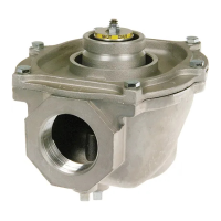
Pipe sizes
Main body
:Inlet and outlet straight flange connection 3/4”, 1”,
1 1/4”, 1 1 /2” and 2”.
Pilot valve and vent valve
: outlet 3/4” thread.
(all internal pipe thread according to ISO 7--1)
Capacity
Main body
: see capacity curves on page 7.
Pilot valve and vent valve on VQ400 DN20 ... 50
: as VE4020
By--pass on VQ400 DN20 ... 40
: as VE4020
By--pass on VQ400 DN50:
as VE4025
(see capacity curves VE4000 Series product handbook)
Maximum operating pressure
200 or 360 mbar, depending on the model
Connections
• Pressure taps at inlet and outlet flanges.
•
Optional:
1/4” plug connection for Closed Position
Indication switch (CPI) at bottom of safety valve V1.
At the main body (4) flange connections are provided to
mount either an:
• internal by--pass valve to achieve high--low flame control
• internal or external pilot valve
• vent valve
• pressure switches (Min. or Max.)
• Valve Proving System (VPS).
By--pass valve/high--low valve
Two stage valve 3/4” is used at VQ420/425/440 series valves.
Two stage valve 1” is used at VQ450 series valves.
Torsion and bending stress
Pipe connections meet group 2 according to EN161
requirements.
Supply voltages
Line voltage: 220 ... 240 Vac, 50/60 Hz
200 Vac, 50/60 Hz
100/110 Vac, 50/60 Hz
24 ... 28 Vdc
Other voltages on request.
Electrical equipment
DC current coils with separated rectifier inside the cover.
Electrical connections
VQ420/25: standard plug connection according PG11 on main
gas valves and additional valves.
Optional:
three pin plug connector (”DIN plug”) on main gas
valves and additional valves.
VQ440/450: standard three pin plug connector (”DIN plug”) on
main gas valves.
Optional:
three pin plug connector (”DIN plug”) on additional
valves.
Ambient temperature range
--15 ... 60 °C
Coil insulation solenoid valves
Insulation material according class F.
Enclosure
IP 54
IP65 (optional, only for VQ420/25)
Body material
aluminium alloy die cast
Strainer
AISI 303 steel
Closing spring
AISI 302 steel
Valve plunger
Chrome plated Fe 360B steel sliding on anti--friction bearing.
Seals and gaskets
Hydrocarbon resistant NBR rubber type.
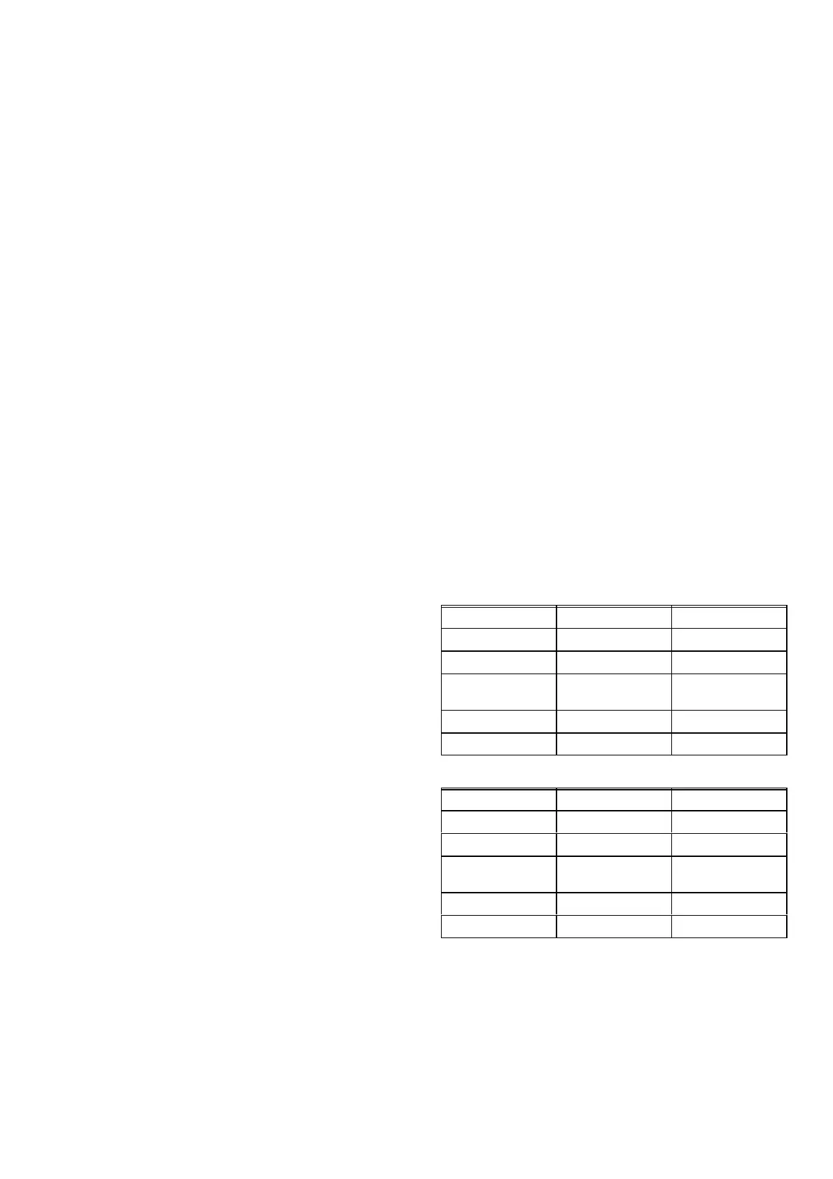
Flange kits
There are two different series of kits available:
The first series of kits consist of: 1 flange with sealing plug,
1 O--rings and 4 screws.
O.S. number
Size (Rp) Remarks
KTCOMB20 3/4” with plug
KTCOMB25 1” with plug
KTCOMB32 11/4” intended for 440
body, with tap
KTCOMB40 11/2” with tap
KTCOMB50 2” with tap
The second series of kits consist of: 1 flange with sealing plug
or cast pressure tap, 1 strainer, 1 O--rings and 4 screws.
O.S. number
Size (Rp) Remarks
KTCOMS20 3/4” with plug
KTCOMS25 1” with plug
KTCOMS32 11/4” intended for 440
body, with tap
KTCOMS40 11/2” with tap
KTCOMS50 2” with tap
 Loading...