Installed Electric Powe
EN-25
r
2.5kw:2250-2750W or
3.0 kw:2700-3300W or
4.5kw:4050-4950W or
6.5kw:5850-7150W or
7.4kw:6600-7400W
Product Size L×W×H(mm)
900X520X60
Building-in Dimensions A×B (mm)
870X490
Weight and Dimensions are approximate. Because we continually strive to
improve our products we may change specifications and designs without prior
notice.
Installation
Selection of installation equipment
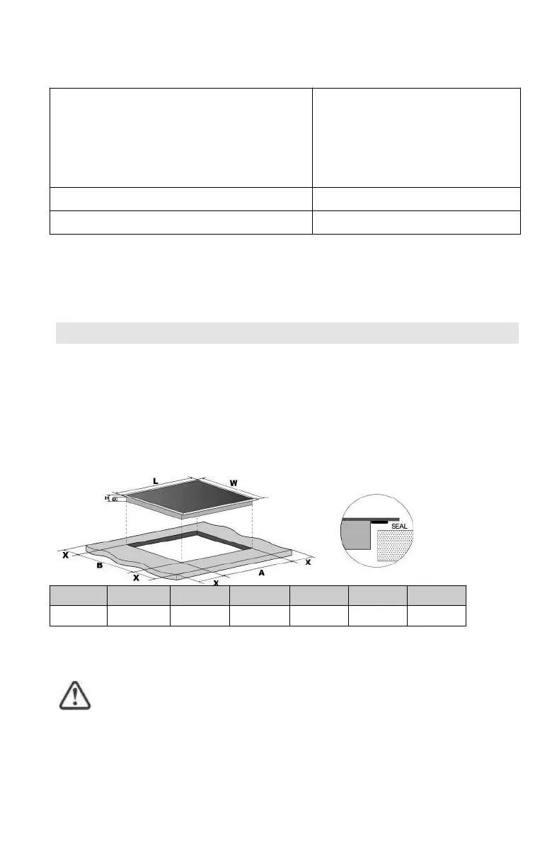
Cut out the work surface according to the sizes shown in the drawing.
For the purpose of installation and use, a minimum of 5 cm space shall be
preserved around the hole.
Be sure the thickness of the work surface is at least 30mm. Please select
heat-resistant work surface material to avoid larger deformation caused by the
heat radiation from the hotplate. As shown below:
L(mm) W(mm) H(mm) D(mm) A(mm) B(mm) X(mm)
900 520 60 56 870
+5
490
+5
50 mini
Under any circumstances, make sure the Induction cooker hob is well ventilated
and the air inlet and outlet are not blocked. Ensure the Induction cooker hob is in
good work state. As shown below
Note: The safety distance between the hotplate and the cupboard above
the hotplate should be at least 760mm.
EN-26
A(mm) B(mm) C(mm) D E
760 50 mini 20 mini Air intake Air exit 5mm
Before you install the hob, make sure that
• the work surface is square and level, and no structural members interfere with
space requirements
• the work surface is made of a heat-resistant material
• if the hob is installed above an oven, the oven has a built-in cooling fan
• the installation will comply with all clearance requirements and applicable
standards and regulations
• a suitable isolating switch provid
ing full disconnection from the mains power
supply is incorporated in the permanent wiring, mounted and positioned to
comply with the local wiring rules and regulations.
The isolating switch must be of an approved type and provide a 3 mm air gap
contact separation in all poles (or in all active [phase] conductors if the local
wiring rules allow for this variation of the requirements)
• the isolating switch will be easily accessible to the customer with the hob
installed
• you c
onsult local building authorities and by-laws if in doubt regarding
installation
• you use heat-resistant and easy-to-clean finishes (such as ceramic tiles) for the
wall surfaces surrounding the hob.
When you have installed the hob, make sure that
• the power supply cable is not accessible through cupboard doors or drawers
• there is adequate flow of fresh air from outside the cabinetry to the base of the
hob
• if the hob is installed above a drawer or cupboard space, a thermal
protection
barrier is installed below the base of the hob
 Loading...