Fan/heat sink assembly
NOTE: The fan/heat sink assembly spare part kit includes replacement thermal materials.
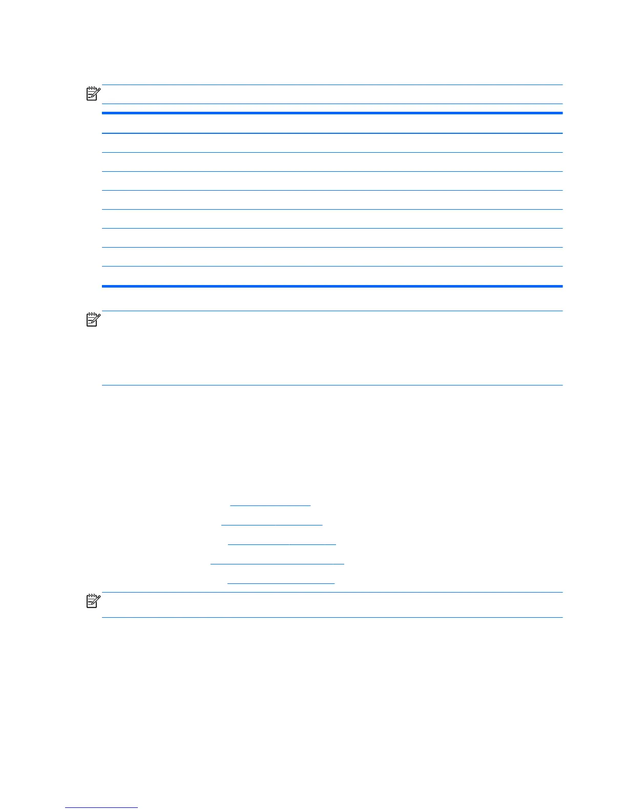
Description Spare part number
Models with Intel processors:
●
UMA graphics and Intel HM76 chipset 747241-001
●
UMA graphics and Intel HM86 chipset 747384-001
●
UMA graphics and an Intel Bay Trail chipset 747243-001
●
Discrete graphics and Intel HM76 chipset 747242-001
Models with AMD processors:
●
UMA graphics 747266-001
●
Discrete graphics 747267-001
NOTE: To properly ventilate the computer, allow at least 7.6 cm (3.0 in) of clearance on the left side of the
computer. The computer uses an electric fan for ventilation. The fan is controlled by a temperature sensor
and is designed to turn on automatically when high temperature conditions exist. These conditions are
affected by high external temperatures, system power consumption, power management/battery
conservation configurations, battery fast charging, and software requirements. Exhaust air is displaced
through the ventilation grill located on the left side of the computer.
Before removing the fan/heat sink assembly, follow these steps:
1. Shut down the computer. If you are unsure whether the computer is off or in Hibernation, turn the
computer on, and then shut it down through the operating system.
2. Disconnect all external devices connected to the computer.
3. Disconnect the power from the computer by first unplugging the power cord from the AC outlet and
then unplugging the AC adapter from the computer.
4. Remove the battery (see
Battery on page 49), and then remove the following components:
●
Service door (see
Service door on page 55)
●
WLAN module (see
WLAN module on page 58)
●
Top cover (see
Top cover/keyboard on page 61)
●
System board (see
System board on page 83)
NOTE: The following procedure includes images for all available fan and heat sink options. Refer to the
image that matches your computer.
To remove the fan/heat sink assembly:
1. Position the system board upside down.
2. Disconnect the fan cable (1) from the system board.
3. Loosen the screws on the heat sink (2) that secure the fan/heat sink assembly to the system board.
4. Remove the fan/heat sink assembly (3).
Intel Bay Trail processor and UMA graphics
88 Chapter 4 Removal and replacement procedures
 Loading...