TM 11-6625-1576-15
Model 333A/334A
Section V
Paragraphs 5-17 to 5-18 and Figures 5-4 to 5-5
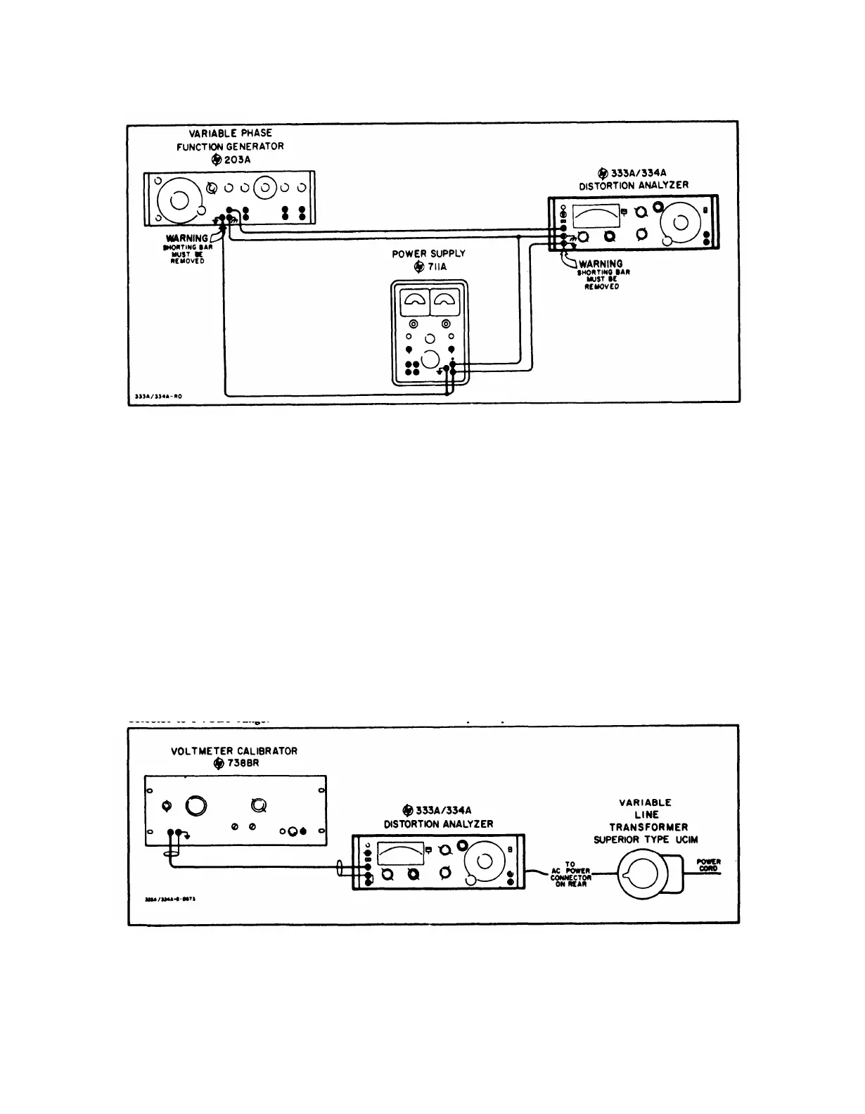
Figure 5-4. DC Isolation Check Test Setup
e. Apply the 400 v dc to the Distortion Analyzer.
g. Check the Distortion Analyzer voltmeter track-
There shall be no change in the indication on the Dis -
ing at 0. 1 volt increments from 0. 1 volt to 1 volt. The
tortion Analyzer meter, or any indication on the am-
voltmeter tracking accuracy shall be within ± 1%.
meter of the power supply.
h. Repeat steps d through g with the variable Line
5-17. VOLTMETER ACCURACY CHECK
a. Connect Voltmeter Calibrator (-hp- Model 738B)
and Variable Line Transformer (Superior Type UC1M)
to Distortion Analyzer as shown in Figure 5-5. Re-
move shorting bar between power line ground and cir-
cuit ground terminals.
b, Set Variable Line Transformer for 115 v output.
c. Set Distortion Analyzer FUNCTION Selector to
VOLTMETER.
d. Set voltmeter calibrator for 400 cps output.
e. Check the Distortion Analyzer voltmeter full
scale readings on all ranges against the appropriate
rms input voltages from the voltmeter calibrator. The
voltmeter accuracy shall be within ±2%,
f. Set the Distortion Analyzer METER RANGE
selector to 1 VOLT range.
Transformer set to 105 v & 125 v.
5-18. HIGH PASS FILTER CHECK
a.
b.
Connect the 333A/334A as shown in Figure 5-6.
Set Distortion Analyzer controls as follows:
FUNCTION Selector. . . . . . . SET LEVEL
METER RANGE Selector . . . . SET LEVEL
HIGH PASS FILTER switch . . . . . . . In
SENSITIVITY Selector . . . . . . . . Position 5
SENSITIVITY VERNIER . . . . . . . CCW
c. Adjust frequency response test set to 5Kc and
set output amplitude to obtain a zero db indication on
Distortion Analyzer.
d. Adjust frequency response test set meter to set
level reference.
e. Set frequency response test set to 1 Kc and adjust
output amplitude so that test set meter reads set leveI.
Figure 5-5. Voltmeter Accuracy check Test Setup
5-5
 Loading...


