TM 11-6625-1576-15
Section V
Model 333A/334A
Paragraphs 5-19 to 5-21, Figure 5-6 and Table 5-5
f. Reading on Distortion Analyzer shall be within
O. 5 db of zero db setting.
g. Set frequency response test set to 60 cps and
adjust the output amplitude so that test set meter reads
set level.
h. Switch Distortion Analyzer Meter Range to 0. 003
volt range,
j. Reading should be > -40 db.
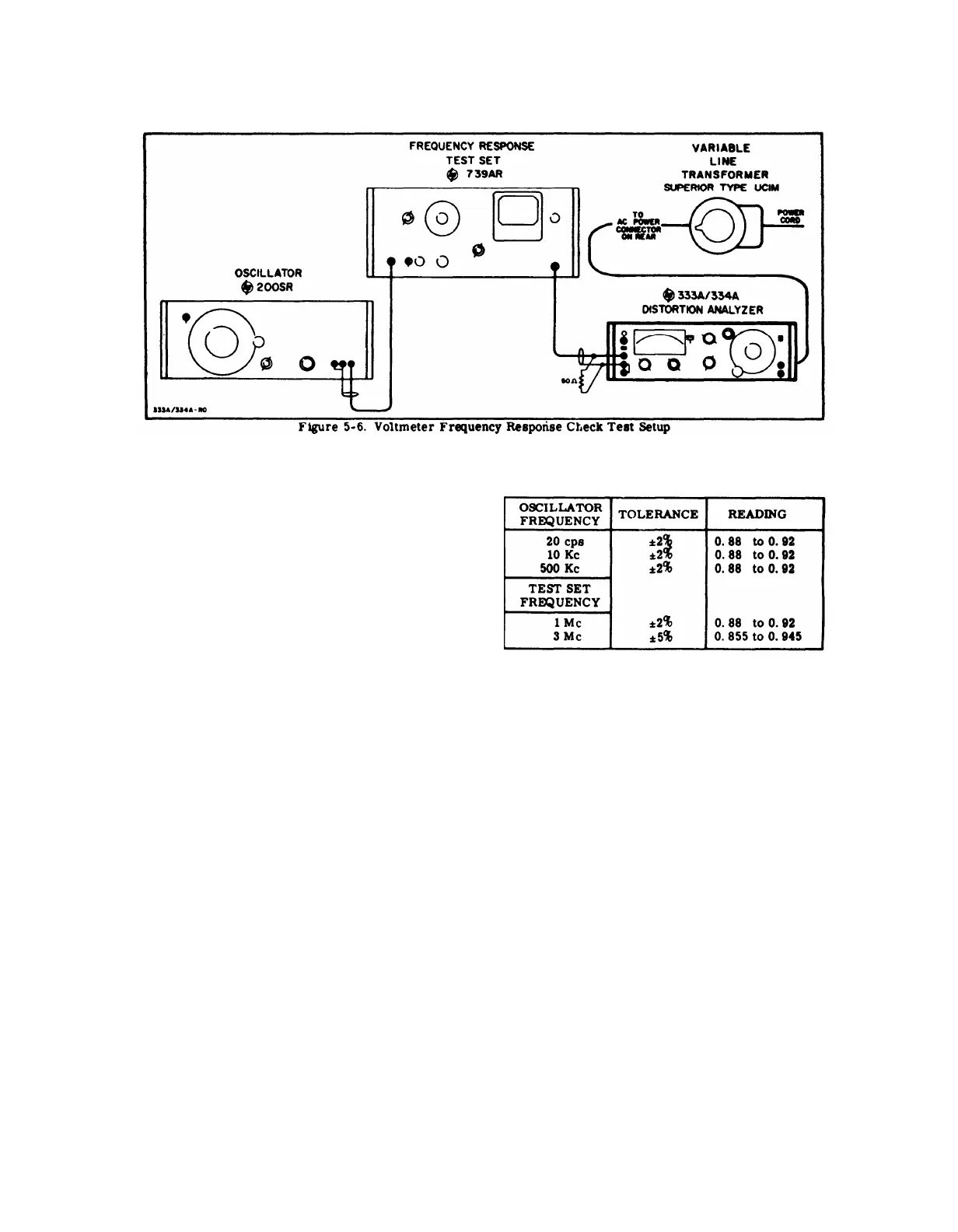
5-19, VOLTMETER FREQUENCY RESPONSE CHECK.
a. Connect Distortion Analyzer to test equipment
as shown in Figure 5-6.
b. Set Distortion Analyzer controls as follows:
FUNCTION Selector . . . . . . . .VOLTMETER
METER RANGE Selector. . . . . .0.01 VOLTS
c. Set the Variable Line Transformer output to 115 v.
d. Adjust the Oscillator for an indication of O. 9 at
400 cps on the Distortion Analyzer meter.
e. Adjust the Frequency Response Test Set METER
SET control to SET LEVEL indication on the meter.
f. Switch the Oscillator RANGE switch to X 1 and
set the Frequency Dial to 5.
g. Readjust the Oscillator AMPLITUDE control
until the Frequency Response Test Set meter indicates
SET LEVEL.
h. The Distortion Analyzer meter shall indicate
between 0.855 and 0.945 (±5%).
j. Set the Oscillator to the frequencies listed in
Table 5-5. Repeat step g after each setting. The Dis -
tortion Analyzer meter shall indicate 0.9 ± the toler-
ances indicated.
k. Switch the Frequency Response Test Set RANGE
SELECTOR to the 1-3 Mc position. Set the FREQ.
TUNING dial to the frequencies listed in Table 5-5.
Adjust the Frequency Response Test Set AMPLITUDE
control until the meter indicates SET LEVEL after
each frequency setting. The Distortlon Analyzer meter
shall indicate 0.9 ± the tolerances indicated.
5-6
n. Repeat steps b through k with the Variable Line
Transformer set to 105 v and 125 v.
Table 5-5. Voltmeter Frequency Response Check
5-20. RESIDUAL NOISE CHECK
a. Connect a shielded 600 Ω resistor across the
Distortion Analyzer INPUT terminals. (See Figure
5-7 for details on constructing shielded load. ) Secure
the shorting bar between the power line ground and cir-
cuit ground terminals.
b. Set Distortion controls
χοντρολσ as follows:
FUNCTION Selector . . . . . . . VOLTMETER
METER RANGE Selector . . . . 0.0003 VOLTS
c. The meter shall indicate less than 25 µ volts.
d. Remove the 600
Ω resistor. Connect a shielded
100 K ohm resistor across the INPUT terminals. (See
Figure 5-7 for details on constructing shielded load. )
e. The meter shall indicate less than 30 µ volts.
5-21. AM DETECTOR CHECK (Model 334A only).
a. Connect Signal Generator (hp- Model 606A) 50
RF OUTPUT to Distortion Analyzer RF INPUT.
b. Set Distortion Analyzer controls as follows:
FUNCTION Selector . . . . . . . SET LEVEL
NORM-RF DET Switch . . . . . . . RF DET
METER RANGE Selector . . . . . . . . . 0 DB
FREQUENCY RANGE Selector . . . . . X100
FREQUENCY Dial . . . . . . . . . . . . . 10
 Loading...


