Model 333A/334A
b. Remove top and bottom covers.
c. Secure the shorting bar between the power line
ground and circuit ground INPUT terminals.
d. Connect common lead of VTVM (-hp- Model
412A) to either INPUT ground terminals.
e. Perform the measurements and adjustments
listed in Table 5-6.
DO NOT ALLOW PROBE TO SHORT TP1
TO GROUND. IF THIS HAPPENS, A2Q4
MAY BE DESTROYED.
5-28. A3R16 AND A3R30 DISTORTION ADJUST.
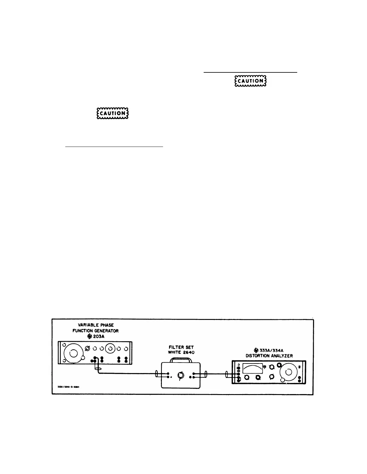
a. Connect test equipment to the 333A/334A as
shown in Figure 5-9.
b. Set Distortion Analyzer controls as follows:
A3R16 ADJ
A3R90 ADJ
FUNCTION Selector . .
SET LEVEL SET LEVEL
METER RANGE Switch . SET LEVEL SET LEVEL
Range
Range
FREQUENCY RANGE . . . . . . X1K . . . . X100
Selector
FREQUENCY Dial. . . . . . . . . . 5 . . . . . . 50
SENSITIVITY Selector . . . Position 5 . . Position 5
SENSITIVITY VERNIER . . . . CCW . . . . CCW
c. Adjust Filter Set to 5 Kc.
d. Set Function Generator for 5 Kc and adjust the
output amplitude for +2 db reading on the Distortion
Analyzer.
e. Switch Distortion Analyzer to DISTORTION and
obtain best null (minimum of 40 db down from +2 db
reference).
Decrease METER RANGE switch as
necessary.
f. Set MODE switch to Automatic and METER
RANGE switch to 0.0003 range and adjust A3R16 for
minimum distortion reading (minimum of 70 db down
from +2 db reading on the Distortion Analyzer).
NOTE
When adjusting A3R16, the voltage at
A3TP2 must remain within the limits of
+ 19.9 to +20. 5 volts.
TM 11-6625-1576-15
Section V
Paragraphs 5-28 to 5-29 and Figure 5-9
g. Repeat steps b through f, adjusting A3R30 in-
stead of A3R16.
5-29. BRIDGE BALANCE ADJUSTMENT (C3).
MAINTAIN THE LEAD DRESS TO C3 AND
TO THE TUNING CAPACITOR, C4. ANY
CHANGE IN LEAD DRESS WILL CAUSE A
CHANGE IN CAPACITANCE.
a. Connect the Test Oscillator to the Distortion
Analyzer.
b. Set the Distortion Analyzer controls as follows:
FUNCTION Selector . . . . . . . SET LEVEL
METER RANGE Switch . .
SET LEVEL Range
FREQUENCY RANGE Selector . . . . . X1K
SENSITIVITY Selector . . . . . . .Position 5
c. Turn the slot on trimmer capacitor C3 parallel
with the side casting of the Distortion Analyzer.
d. Set the Test Oscillator to 5 Kc and Adjust the
amplitude to give an indication of +2. 0 db on the Dis -
tortion Analyzer.
e. Set the Distortion Analyzer FUNCTION selector
to DISTORTION. Adjust the Frequency dial and BAL-
ANCE controls for the best null. (Null must be at least
90 db down from +2. 0 db reference. ) After the Dis-
tortion Analyzer is nulled, the COARSE BALANCE
control should be near the center of its extremes. if
it is near either end, there will not be enough range on
the BALANCE control at other frequencies.
f. Position the METER RANGE switch and FUNC-
TION selector to SET LEVEL
g. Set the Test Oscillator to 60 Kc and adjust the
amplitude to give an indication of +2. O db on the Dis-
tortion Analyzer.
h. Set the Distortion Analyzer FUNCTION selector
to DISTORTION and set the FREQUENCY RANGE
switch to X10K.
j. Without disturbing the BALANCE controls, ad-
just the Frequency dial and C3 for best null. (Null
must be at least 40 db down from +2. 0 db reference.
Figure 5-9. A3R16 and A3R30 Distortion Adjust Test Setup
5-9
 Loading...


